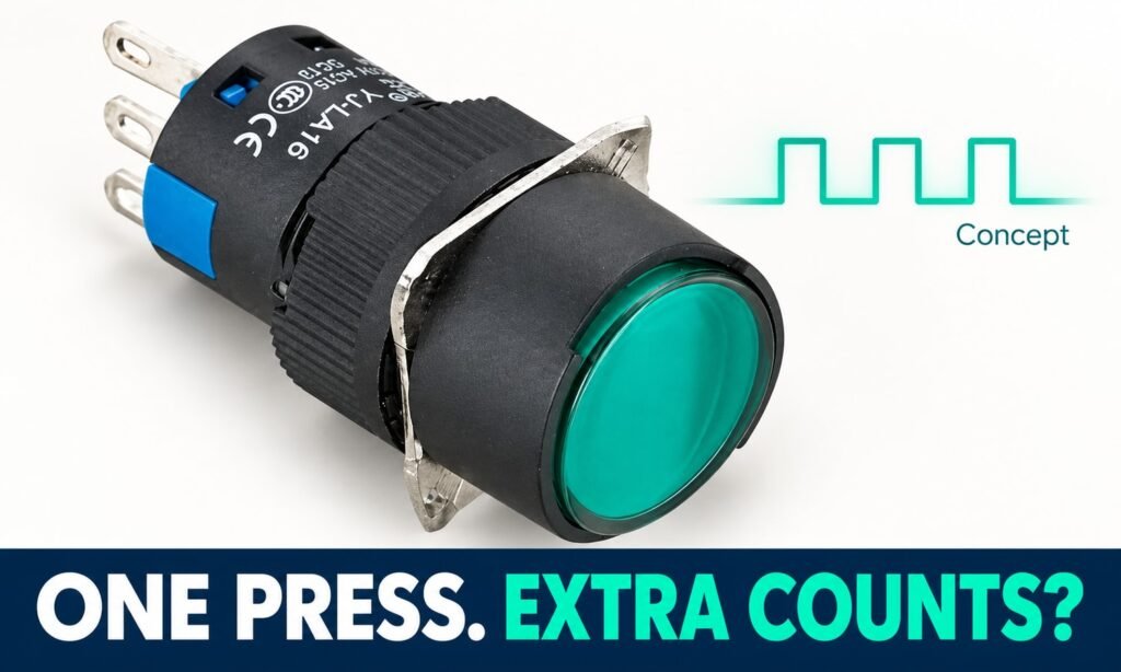
AI-composed illustration based on YIJIA product references; not a specification drawing.
If one button press produces extra counts, trace the event through the contact circuit, input module and program. Contact bounce is one possibility; electrical noise and event-handling logic can also matter. First define what one accepted operation should produce, then identify where the observed behavior differs.
Input filtering can reject brief transitions, but it can also reject a valid short operation. The goal is to preserve the required response while addressing the cause, using the actual module documentation and a defined press, hold, release and repeat sequence.
Separate the physical press from the recorded event
The operator performs a mechanical action. The switch changes an electrical contact state. The input device recognizes a state according to its documented behavior, and the program determines how that state is used. A counter may therefore be responding to information that has already passed through several stages. Describing the entire chain simply as “the button signal” can obscure where the problem occurs.
Begin with the intended behavior: for example, one accepted event for each deliberate operation. Define what constitutes a new operation and when another event is allowed. This is a functional requirement for the equipment, not a universal property of a push button. Without that definition, it is difficult to distinguish unwanted repeated recognition from behavior the program was designed to perform.
Record the actual symptom precisely. Does the count increase twice on a press, on release, during a long hold or at an unrelated moment? Does it occur every time or only under certain operating conditions? These observations guide the investigation. They do not independently prove contact bounce, but they are more useful than an initial assumption that the switch is too sensitive.
Understand what contact bounce evidence supports
Rockwell Automation’s Embedded I/O technical data explains that input filtering can limit the effect of transients caused by contact bounce or electrical noise. The statement supports considering both the switching contact and the input’s response. It does not assign a universal bounce duration to every switch or establish that every counting problem has the same cause.
Also distinguish a contact’s electrical suitability from its transition behavior. A switch can have a defined mechanical action while still needing evaluation for the input circuit’s electrical requirements. The guide to contacts for PLC and low-current inputs addresses that selection question. It should be reviewed separately from the timing and event-recognition issue discussed here.
Identify the actual input path
Record the complete input module or counter reference and the channel being used. Obtain the applicable documentation and current configuration. A device family name is not enough to establish available filtering behavior or timing. Keep the wiring reference, input reference and program reference together so observations from one stage are not accidentally associated with another channel.
Determine what information is available at each stage. The displayed program state may already reflect input filtering and processing; it is not necessarily a direct view of the raw contact transition. Conversely, a physical observation of the switch says little about how the counter interprets the input. The investigation needs evidence appropriate to the stage being evaluated.
Where signal measurement is necessary, qualified personnel should use an appropriate method for the circuit and equipment. Record the operating condition and measurement location along with the result. A waveform without that context can be misleading, particularly if it is taken at a different point from the input under review. Use the equipment’s approved diagnostic procedures.
What an input filter changes
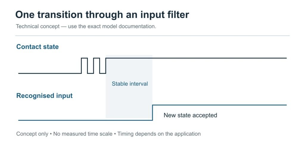
A filter can require the input to remain in a new state for a defined period before the device reports that change. Rockwell’s input-filter configuration documentation explains this behavior for specified modules. It also distinguishes filter settings from other hardware and supply-related delays. The particular settings belong to those devices, not to all PLC inputs.
The consequence is a trade-off to assess against the application. A brief unwanted transition may not be recognized, but a brief valid input may also fail to meet the configured requirement. Increasing a filter time is therefore not automatically an improvement. The setting must support the intended operator action and equipment response, with the behavior verified for the selected module and program.
Check whether the device allows different handling of off-to-on and on-to-off transitions. Read its actual documentation rather than assuming a single setting applies equally to both. The release behavior may matter to recognising the next operation. A change that appears to correct the press transition should still be assessed through the complete press, hold and release sequence.
Technical concept; not a product test or installation drawing.
Review the program’s definition of an event
Ask how the application converts an input state into a count or command. A state that remains active and a newly recognized transition are different kinds of information. The program should be reviewed against the intended operating sequence. This review belongs with the equipment’s programming requirements and the controller documentation, not with a generic assumption that every counter treats an input identically.
Describe long holds and repeated deliberate presses as separate test conditions. The required behavior during a hold may differ from the behavior on a new operation after release. If those cases were never defined, a program can appear correct during a quick demonstration while producing unexpected results in normal use. Make the expected result explicit before changing the implementation.
Keep electrical noise as a separate possibility
Contact bounce and electrical noise are not interchangeable explanations. A symptom that occurs without a deliberate press, or in association with another equipment event, warrants a review of the broader signal path. Those observations are clues, not a diagnosis. Review the relevant wiring and device requirements through the equipment’s troubleshooting process rather than assigning every irregular transition to the button.
The actual contact configuration should also match the circuit design. Confirm the full button code, terminal assignment and reference state. If a replacement or wiring change preceded the problem, compare the current arrangement with the approved record. A timing adjustment should not be used to compensate for an unresolved configuration or connection mismatch.
Avoid claiming that one terminal style, housing material or mechanical action eliminates all unwanted transitions. Those features do not independently establish the complete signal behavior. A product claim about bounce or input compatibility needs relevant evidence. In its absence, discuss the configuration and validation requirements rather than describing a particular series as inherently free from timing problems.
Define one event and test the complete operating sequence
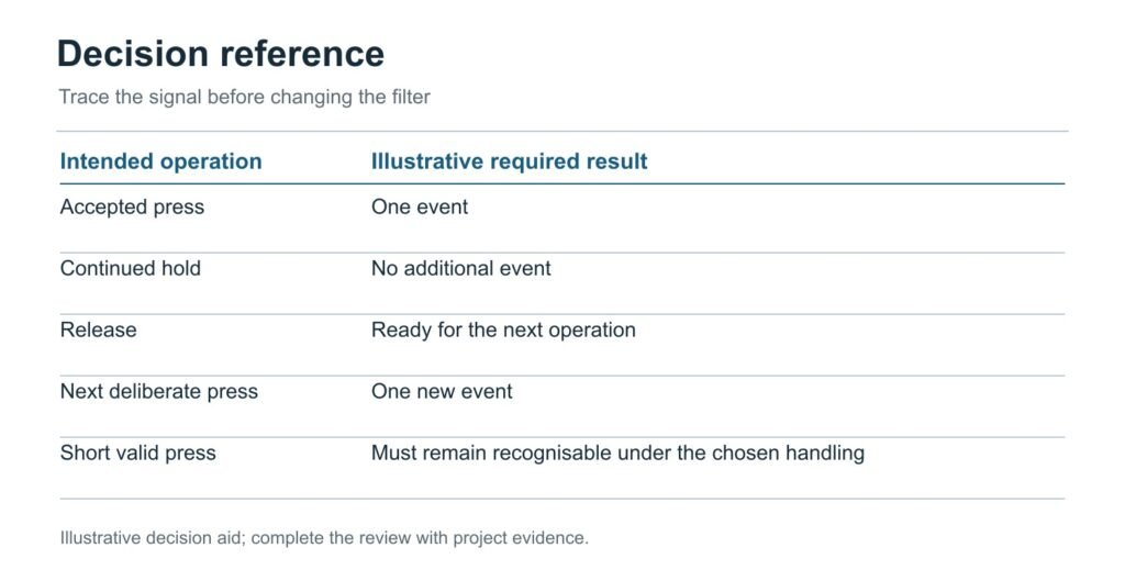
Write the expected event sequence before changing an input filter. For a simple one-count-per-press requirement, an accepted press creates one event, holding the button creates no additional events, and release prepares the system for the next deliberate press. This is an illustrative functional requirement, not a universal counter configuration. The equipment designer must decide whether it describes the actual task.
Use that requirement to distinguish two different complaints. If the count increases continuously while the input remains active, review how the program treats an active state. If several recognised transitions occur around one operation, review the signal path and input handling. Neither observation alone proves a defective button. They point to different evidence and different parts of the system to examine.
The filter question is then concrete: which unwanted transitions should be rejected, and which deliberate operations must still be accepted? Compare their relevant timing with the behavior documented for the actual input module. A setting that removes extra counts by also rejecting a valid short press has not satisfied the requirement. Response and rejection need to be assessed together.
Use separate cases for a normal press, the shortest intended press, a longer hold, release and the fastest intended repeat operation. For each case, record the expected input response and application result. Avoid inventing a universal press duration. The intended operator interaction and equipment response determine which cases are meaningful for the project.
Also examine the condition in which the reported fault occurs. If extra events appear when another part of the equipment operates, include that condition in the investigation rather than testing only a quiet bench arrangement. The evidence may point to electrical noise or another signal-path issue. A delay should not be used to conceal an unresolved connection or configuration problem.
Keep the input observation and application result in separate columns. The module may report a stable state while the program handles it incorrectly, or the final count may look correct during a sequence that did not exercise the problematic transition. The two records help identify where the requirement is met and where further work is needed.
Once the behavior is accepted, retain the switch code, input module, filter configuration and relevant program revision with the test conditions. This record supports later substitutions: a different button or input version can be assessed against the same functional requirement. It also explains why the chosen timing was used, instead of leaving maintenance staff with an unexplained delay to copy into future equipment.
Decision aid based on the article; examples are illustrative, not customer or test records.
Frequently asked questions
Is double counting always caused by contact bounce?
No. The contact, electrical signal path, input settings and program behavior all need consideration. Start by identifying when the extra event occurs and how the application recognises an event. Obtain evidence at the relevant stages before assigning a cause. Replacing the button without that review may leave the actual problem unchanged.
What debounce time should I use?
There is no universal value for every button and input. The appropriate handling depends on the actual signal, module behavior, valid operation duration and response requirements. Use the applicable documentation and evaluation results. Do not treat a timing example from another controller or a conceptual waveform as a specification for your equipment.
Does a longer filter always give a more reliable result?
Not if it prevents a valid operation from being recognised or produces an unacceptable delay. Filtering should reject unwanted behavior while preserving the required input response. Assess both aspects. Verify the complete operating sequence, including release and the next deliberate operation, rather than judging the setting only by whether one visible symptom disappears.
Discuss the button and input together
For a YIJIA LA16 configuration, send the contact requirement and input details with the intended command or counting behavior. Include the module reference and relevant circuit conditions. Request the available product information without assuming a bounce duration or universal compatibility that has not been established for the proposed configuration.
Momentary push button switches are everywhere. They are simple, reliable, and incredibly versatile. Whether you’re designing consumer electronics, industrial control panels, or hobby projects, these tiny devices can make a big impact. In this article, we’ll explore what momentary push button switches are, how they work, common applications, and key considerations for selecting the right […]
Yijia Product Brochure.zip In the field of industrial production, the degree of automation is getting higher and higher, and industrial robots, as an important production tool, have been widely used in various industries. In order to meet the demanding control requirements of industrial robots, Yijia has introduced the GQ19A series of push-button switches designed specifically […]
Basic function: By using a metal push rod to move or separate the moving/stationary contacts, the current can be controlled to turn on or off, and the circuit can be turned on or off. Its contact types include normally open (NO), normally closed (NC), and composite (NO+NC combination).Reset function: It can be divided into self […]
We use cookies to enhance your browsing experience, serve personalised ads or content, and analyse our traffic. By clicking "Accept All", you consent to our use of cookies.