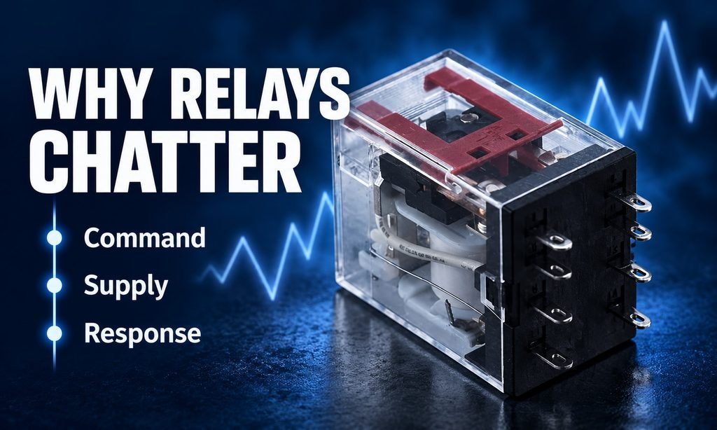
A chattering control relay needs a review of three things at the same event: the command, the coil supply and the relay response. The relay may be following an unstable command, receiving unsuitable supply conditions or have a component or installation problem. Sound alone cannot distinguish them.
Start with the complete relay and socket codes, then follow the evidence. This guide explains what to collect and how the findings change the next action, so a replacement addresses a defined problem rather than becoming another trial substitution.
Distinguish the symptom from the diagnosis
Record whether the relay appears to operate repeatedly, fails to remain operated or makes a sound while its state appears steady. Note whether the associated equipment also changes state. Avoid writing “bad relay” as the initial fault description. That label converts an untested explanation into an apparent fact and can steer purchasing towards replacement before the circuit has been assessed.
Identify when the symptom occurs. It may be reported during startup, when another load operates, after a control change or only under certain equipment conditions. These observations help determine what information the responsible engineer needs. A condition-specific fault should not be assessed only from a record taken when the equipment is idle and the relay behaves normally.
Keep the distinction between observed relay behavior and the state of a visible indicator. A status lamp may provide useful information, but its meaning depends on the device and circuit. It should not automatically be treated as proof of the exact contact behavior. Use the relay documentation and the equipment’s approved diagnostic methods to establish what each observation represents.
Confirm the complete relay and socket
Record the relay’s full code and coil marking, together with the socket or base code where applicable. A family name or pin count is not a complete specification. Different versions can have different coil requirements or terminal arrangements. If a replacement was recently installed, compare its complete identification with the approved equipment record rather than assuming it matches because it fits the socket.
Review the relay and socket diagrams as a pair. Check that the equipment documentation refers to the installed versions and any fitted accessories. The relay and socket selection guide explains why physical fit alone is insufficient. Use it to structure the comparison, then obtain the diagrams for the actual components involved in the reported fault.
Also record any recent work on connections, control devices or suppression accessories. A change elsewhere in the circuit may coincide with the symptom even if the relay itself was untouched. The maintenance history is therefore part of the evidence. It can help the investigation focus on a changed condition instead of repeatedly replacing the most audible component.
Examine supply behavior during the event
OMRON’s general-purpose relay troubleshooting guide identifies voltage drop as a possible contributor to imperfect operation and contact chattering. It also lists supply ripple, coil specification and other conditions in its troubleshooting discussion. These are investigation directions, not a diagnosis for every installation. Their relevance must be established against the actual circuit and relay documentation.
The nominal supply label is only the starting point. Determine what supply conditions reach the coil during the reported event and compare them with the requirements of that exact relay. Where measurements are needed, qualified personnel should obtain them using appropriate procedures. A single number without the equipment state, measurement context or relevant specification may be insufficient to explain intermittent behavior.
Do not adopt a universal percentage of rated voltage as the pass-or-fail threshold. Operate and release characteristics belong to the model and its stated conditions. A value mentioned in a general example for another relay is not a specification for the installed part. Request the applicable data and keep it with the findings before concluding that the supply is acceptable or inadequate.
Check whether the command itself is changing
An unstable command can cause repeated operation without a mechanical defect in the relay. Review the control signal and the logic or device that generates it. Establish whether the relay is responding to repeated commands or failing to follow a steady command. Those are different problems and can lead to different corrective actions, even when the audible symptom sounds similar.
Use the equipment’s diagnostic records where available, while recognizing what they do and do not show. A controller indication may describe the commanded state rather than every electrical condition at the coil. Correlate the relevant observations instead of relying on one screen or one lamp. The aim is to establish a consistent account of the command, supply and relay response during the fault.
Technical concept; not a product test or installation drawing.
Review connections and installation conditions
Connections and socket engagement belong in the inspection, particularly after replacement or maintenance. Have the responsible personnel compare the installation with the applicable instructions using the equipment’s isolation and inspection procedures. This is not a reason to tighten, move or test components indiscriminately. Record any confirmed discrepancy so the action taken can be linked to an observed condition.
The environment and mechanical installation may also be relevant. Describe unusual vibration, damage or changes around the relay rather than assuming the problem is purely electrical. OMRON’s troubleshooting material includes several possible mechanical and electrical contributors to relay problems. The appropriate response is to investigate the conditions supported by the evidence, not to treat every listed possibility as equally likely.
Do not open a sealed relay case as a routine diagnostic step. A general-purpose relay troubleshooting guide is not an authorization to dismantle a component or return an altered part to service. Use the manufacturer’s instructions and the equipment’s maintenance process to decide how a suspect component should be evaluated, replaced or retained for further examination.
Separate coil behavior from contact-load questions
The coil operates the mechanism, while the contacts serve the switched circuit. Both sides matter, but their specifications are different. Do not use a contact current rating as evidence that the coil supply is correct. Equally, a correctly specified coil does not establish that the contact duty is suitable. Keep the two sets of information separate in the fault report.
Where the investigation identifies contact-side concerns, compare the actual load conditions with the applicable relay data. Do not assume that a relay with a larger advertised current automatically resolves every issue. The equipment may require a review of the duty, switching conditions or other design details. A replacement recommendation should explain which verified mismatch it addresses.
If an accessory or protection arrangement is changed, review its compatibility with the relay and control circuit. The effect must be assessed for the actual application, not inferred from a general claim that suppression is always beneficial. Keep the approved configuration documented so that maintenance personnel do not later fit a different accessory without recognizing that it changes the evaluated arrangement.
Use command and coil evidence to choose the next action
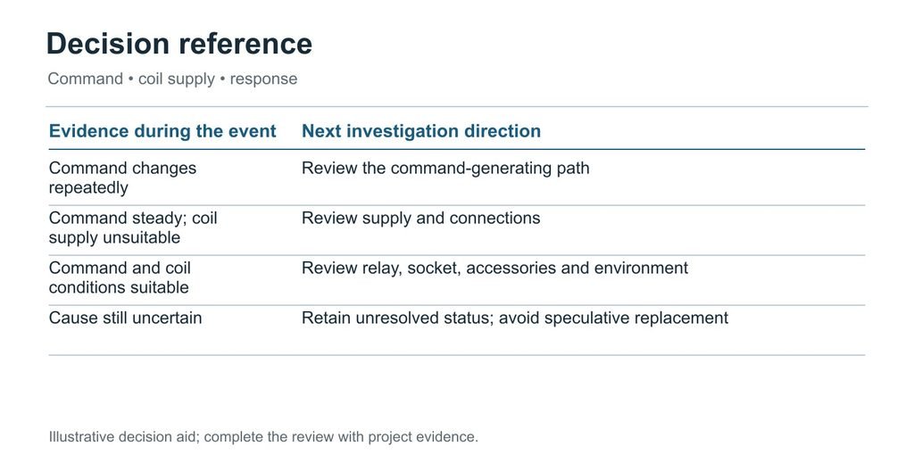
Organise the investigation around three observations: the commanded state, the conditions at the coil and the relay’s response. They need to refer to the same event. A command record from one operating state and a supply reading from another can appear consistent without describing the moment the chatter occurs. Ask the responsible engineer to correlate the evidence before selecting a corrective action.
If the command repeatedly changes, establish why the control system is requesting those changes. The relay may be following the input it receives. Review the relevant sensor, switch or sequence condition through the equipment’s diagnostic process. Replacing the relay will not correct an unstable command unless the investigation separately identifies a relay defect. Preserve the intended control function while addressing its cause.
If the command remains steady but the coil supply departs from the requirements for the installed model, review the supply and connection path. Record the condition in which the departure occurs, including any associated equipment event. The correct comparison is with the relay’s applicable operate, release and supply information, not a generic percentage copied from another relay family.
If the command and coil conditions meet the documented requirements, the investigation can focus more closely on the installed relay, socket, accessories and environment. That still does not make the relay defective by elimination alone. Check the complete configuration and the observations supported by the manufacturer’s troubleshooting process. Document what has been established and what remains uncertain.
Consider a hypothetical report stating that the symptom appears only when another large load starts. This timing is useful because it identifies an event to examine, but it is not proof of a voltage drop. Engineering needs evidence from that event. The report should preserve the association without turning it into a confirmed cause before the relevant conditions have been assessed.
A replacement request should explain its purpose. “Replace the damaged relay with the approved code” differs from “propose a relay for a revised coil supply” and from “assess an alternative socket arrangement.” Include the complete relay and socket references in each case. The YIJIA relay page is an enquiry entry point; request the model-specific data needed for the actual decision.
After the approved action, verify the operating states that produced the complaint, not only an idle condition. Record the accepted parts, any changes and the relevant observations. If the symptom persists, the record should show which hypothesis was tested and what was learned. This prevents the next investigation from repeating the same substitution without resolving the underlying question.
Decision aid based on the article; examples are illustrative, not customer or test records.
Frequently asked questions
Does humming mean the relay is defective?
Sound alone is insufficient to decide. Identify whether the mechanism is repeatedly operating or whether the reported sound occurs with a steady state, then review the supply, coil specification and relevant conditions. Use the manufacturer’s guidance for the actual relay. Avoid treating every audible observation as the same failure mode or dismissing a changed sound without investigation.
Can I fit a higher-voltage coil to stop chatter?
Do not change the coil specification as a trial remedy. The coil must match the control supply and documented operating conditions. A different rated coil can create another mismatch rather than address the cause. Establish what happens at the installed coil during the event, then select any replacement through a documented compatibility review.
What if a new relay shows the same symptom?
That result is a reason to review the external conditions and the correctness of the replacement specification. It is not proof that every relay is defective or that the circuit is healthy. Compare the command, supply, connections and operating context, and retain the exact component references so the investigation can distinguish repeated conditions from component variation.
Send a focused relay enquiry
Contact YIJIA with the complete relay and socket codes, coil supply, contact duty and a description of when the symptom occurs. Include the relevant schematic and recent changes where available. Ask for the documentation needed to assess a candidate configuration. A focused report supports selection without pretending that a sound recording or product photograph alone establishes the cause.
When you design or source components for vehicles, you need switches that can survive vibration, dust, moisture and constant use. YJ metal push button switches are well‑suited for many automotive applications, from engine start buttons to light control, as long as you select the proper rating, sealing and installation method for your project. Why Automotive […]
In today’s industrial automation landscape, Metal Push Button Switch play a critical role in delivering reliable control and quick human feedback on complex systems. This article explores their key benefits, selection criteria, and practical deployment considerations for B2B buyers such as system integrators, OEMs, and maintenance engineers. By focusing on durability, IP/IK protection, and easy […]
Limit switches may be small components in industrial systems, but they play a big role in ensuring precision, safety, and automation reliability. Whether you’re running a large manufacturing line, designing material-handling equipment, or integrating IoT-enabled control systems, choosing the right limit switch can dramatically improve performance and reduce maintenance costs. In this guide, we’ll take a deep […]
We use cookies to enhance your browsing experience, serve personalised ads or content, and analyse our traffic. By clicking "Accept All", you consent to our use of cookies.