When an LED panel indicator glows after an off command, first distinguish full illumination from a faint glow and identify what the light is supposed to mean. A stopped machine does not necessarily have a disconnected lamp supply. Leakage current is one possible cause of unwanted glow, but the actual output and indicator must be assessed together.
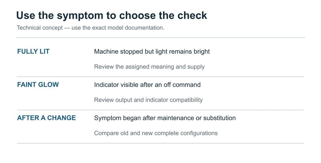
Use the symptom to choose the next check: indication meaning, a recent substitution, or the electrical interface. That is more useful than replacing the lamp repeatedly before establishing which condition is wrong.
Describe the symptom precisely
Record whether the indicator glows continuously, flashes occasionally or remains visible briefly after a command changes. Note whether it occurs only during a particular equipment state or after a recent wiring or component change. A description such as “the light does not work” loses information that can help distinguish an indication problem from a supply or control-output problem.
Also compare the reported glow with the normal illuminated state under consistent viewing conditions. A photograph can be useful for documentation, but camera exposure and ambient lighting can make brightness comparisons misleading. Do not use a photograph as an electrical measurement. Its purpose is to communicate the symptom and the affected panel position, alongside the relevant circuit information.
Identify the full indicator marking, the equipment reference and the expected meaning of the light. If several similar lamps are installed, record exactly which one is affected. This prevents a supplier from reviewing the voltage or connection details of a neighbouring indicator. Keep the symptom description with the same reference used on the equipment drawing and maintenance record.
Understand what leakage-current evidence can establish
Schneider Electric discusses leakage-current-related issues for a particular LED pilot light in its 9001KP38LG technical FAQ. That is useful evidence that lamp and circuit interaction can matter when an indicator is expected to be off. It does not establish that every faint glow has the same cause or that another manufacturer’s indicator has the same internal circuit.
The practical implication is to examine the output and the connected indicator together. An off command is a logical state; it is not enough information to describe every electrical condition at a connected device. Obtain the output device documentation and compare it with the indicator requirements. The relevant question is whether their documented behavior is compatible in both the on and off states.
Avoid translating a manufacturer’s example into an automatic modification. A proposed additional component can affect circuit behavior, loading and heat, and its suitability depends on the actual design. There is no universal resistor value in this guide. Any circuit change needs an engineering assessment based on the specific output, supply, indicator and equipment requirements.
Confirm the intended indication first
Read the lamp’s function from the schematic and operating description. If it indicates that a supply is available, it may legitimately remain illuminated while the machine is stopped. If it indicates a command, it may not prove that the downstream device has responded. Confusing these meanings can lead to replacing a functioning indicator while leaving the panel description or expectation incorrect.
For an illuminated push button, review the lamp and contacts separately. The operator may change the contact state while the lamp receives another signal. The LA16 contact and LED connection guide explains why the terminal assignment and lamp meaning must be tied to the actual version. Do not assume that pressing or releasing the button directly determines every illuminated state.
If the intended meaning is unclear, resolve it with the equipment designer or responsible engineering team. The correct remedy may involve documentation, wiring or control logic rather than a different lamp. Purchasing should receive the clarified indication requirement, not just a request to buy a brighter, dimmer or higher-voltage replacement in the hope that the symptom disappears.
Check the supply and output documentation
Confirm the indicator’s specified supply and whether its documented use is AC, DC or both. Record the actual circuit supply separately from the product marking. A familiar nominal voltage written on two devices does not establish their complete compatibility. The output characteristics and the indicator’s required operating conditions still need to be considered together.
Identify the device that controls the lamp: for example, the relevant controller output or switching component shown on the schematic. Obtain the complete part reference and its documentation. Ask which on-state and off-state characteristics need checking against the indicator. This turns a general complaint into a specific interface review that the equipment engineer or component supplier can evaluate.
Technical concept; not a product test or installation drawing.
Review wiring changes and component substitutions
Compare the present connections with the approved drawing, particularly if the glow began after maintenance. Record any changed indicator, output module, connector or wiring arrangement. Do not assume that a part with the same front appearance has the same lamp specification. A replacement may require a separate compatibility review even when it fits the existing panel opening.
Check whether the symptom affects one position or several positions sharing a control arrangement. That observation can help focus the investigation, although it does not independently identify the cause. Keep the distinction between observation and diagnosis: “three indicators on this output group show a faint glow” is evidence; “all three indicators are faulty” is a conclusion that still needs support.
A controlled comparison may be useful when designed by the responsible engineer. Define what it is intended to distinguish and record the conditions and component versions. An undocumented swap can introduce another variable and make the result hard to interpret. Do not use a temporary disappearance of the symptom as proof that every underlying compatibility question has been resolved.
Decide what information would justify replacement
Replacement becomes a reasoned choice when the existing component is shown to be unsuitable or faulty under the relevant conditions, or when a documented alternative addresses the defined requirement. The decision should identify the evidence and the required behavior. Without that explanation, repeated substitutions can become an expensive sequence of guesses rather than a correction to a known problem.
For a proposed replacement, compare supply, mounting, connections, intended indication and relevant output compatibility. Ask for any documented characteristics needed to assess the off state. If the supplier cannot confirm a required characteristic, retain it as an open item. Do not fill the gap by assuming that a general label such as “anti-interference” guarantees the desired result.
The YIJIA AD16 product page includes a model explanation covering different functions and voltage options. It also states that some combinations in the explanation do not correspond to actual products. Use the page to begin a configuration enquiry, then request confirmation of the complete code. A type-code letter alone is not proof of a solution to a particular faint-glow problem.
Follow the branch that matches the observed behavior
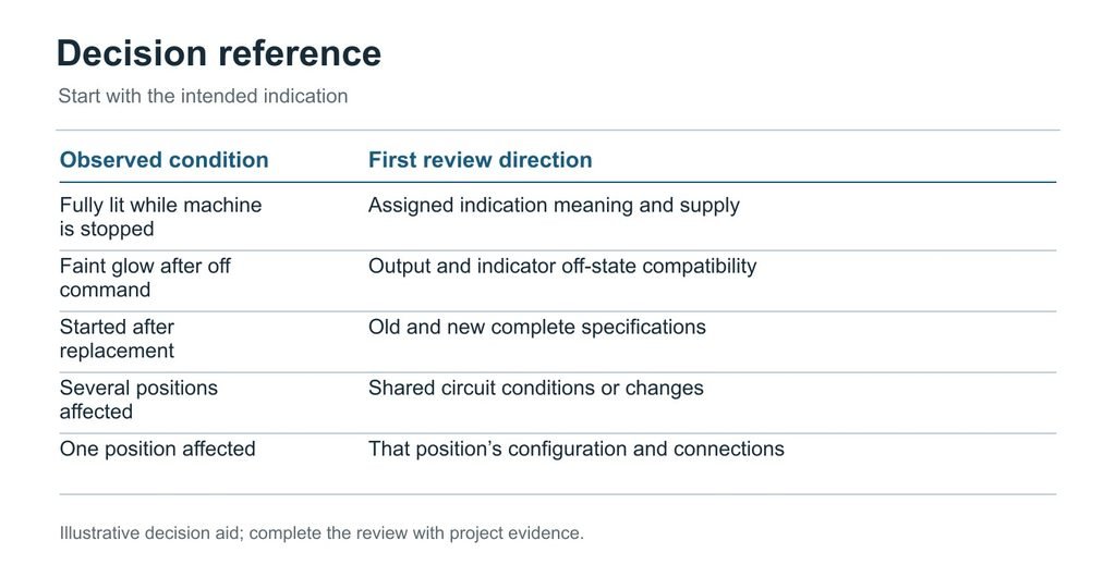
If the indicator stays fully illuminated while the machine is stopped, first review its assigned meaning. A light wired to show available power can remain on while the process is idle. Compare the schematic, panel legend and operating description. If they describe different meanings, resolve that disagreement before treating the lamp as defective. The observation may be correct while the operator’s expectation is not.
If the indicator is only faintly visible after an off command, identify the controlling output and the exact lamp version. Ask engineering to compare the output’s documented off-state behavior with the lamp’s requirements. Leakage current is one possible explanation, supported by manufacturer guidance for some indicators. It remains a hypothesis until the installed circuit and operating conditions support it.
If the symptom began immediately after a replacement, compare the old and new part references. Check the supply specification, connection arrangement and any changed accessory. A common opening size does not establish the same electrical interface. Keep the old part identification and the replacement quotation with the report; they may reveal a substitution that was invisible from the panel front.
If several indicators show the symptom together, record what they share: a supply, output group, operating event or recent modification. This is a useful way to narrow the review, not proof of a shared cause. If only one position is affected, collect the same information for that position rather than assuming the indicator must be the failed component.
The first supplier enquiry should contain enough information to distinguish these branches. Include the full indicator code, the controlling-device reference, the intended meaning, the relevant schematic section and the condition in which the unwanted glow occurs. Add suitably obtained observations or measurements with their context. “The green light stays on” does not tell the supplier whether the complaint concerns full illumination, faint glow or an incorrect status meaning.
Before evaluating a correction, define both the desired off state and the required normal on state. A modification that removes the faint glow but makes the normal indication unsuitable has not met the requirement. Assess the whole indication function under the relevant equipment states, then retain the accepted component and circuit configuration in the equipment record.
Use the evidence to decide between correcting an indication description, reviewing a circuit interface and selecting another indicator. These are different actions with different costs. The YIJIA AD16 product information can help identify the configuration to discuss, but a code label alone should not replace the interface review. Request the exact available version against the clarified requirement.
Decision aid based on the article; examples are illustrative, not customer or test records.
Frequently asked questions
Does a faint glow mean the controlled load is energized?
The indicator alone cannot answer that. Its circuit may represent a command, an available supply or another signal rather than the actual load state. Determine the intended indication and use the equipment’s appropriate verification method. Do not infer the condition of a downstream device solely from a faint light on the panel.
Should I install a resistor across the indicator?
Do not select that modification from a generic internet recommendation. Whether an additional component is appropriate depends on the supply, output, indicator and equipment design. It requires assessment of its electrical and thermal effects as well as the desired indication. Obtain a documented engineering solution instead of treating one resistor value as suitable for every panel.
Will a higher-voltage indicator remove the problem?
Changing the lamp voltage without assessing the complete interface can make the normal indication unsuitable or leave other requirements unmet. The replacement must match the specified supply and behavior. Identify the cause of the unwanted glow first, then compare a proposed solution against the operating conditions instead of choosing a different voltage by trial and error.
Discuss the indicator requirements
Send YIJIA the indicator and circuit information, including the complete code, supply, output device, intended meaning and observed symptom. Ask which available configuration can be assessed against those requirements. A precise report supports a useful technical discussion without assuming that the lamp is defective or promising that an unverified replacement will solve the problem.
Limit switches may be small, but in industrial automation they play an outsized role. If you have ever wondered how heavy machinery knows when to stop, when to change direction, or how far a component can travel without damage, limit switches are often the silent heroes behind those decisions. In modern factories—where uptime, precision, and […]
When you design or source components for vehicles, you need switches that can survive vibration, dust, moisture and constant use. YJ metal push button switches are well‑suited for many automotive applications, from engine start buttons to light control, as long as you select the proper rating, sealing and installation method for your project. Why Automotive […]
Yijia Product Brochure.zip In the field of industrial production, the degree of automation is getting higher and higher, and industrial robots, as an important production tool, have been widely used in various industries. In order to meet the demanding control requirements of industrial robots, Yijia has introduced the Limit switch series of push-button switch designed […]
We use cookies to enhance your browsing experience, serve personalised ads or content, and analyse our traffic. By clicking "Accept All", you consent to our use of cookies.