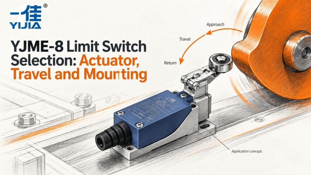
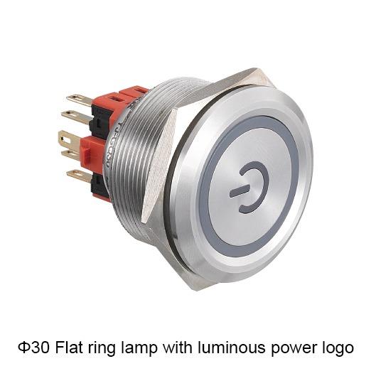
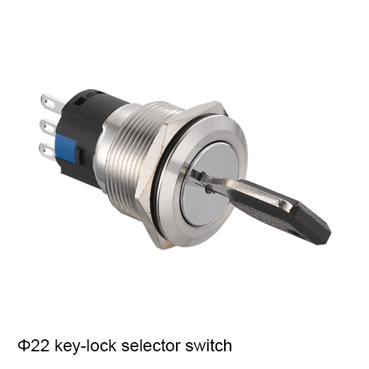
Concept illustration. Use the exact model documents for product details and installation.
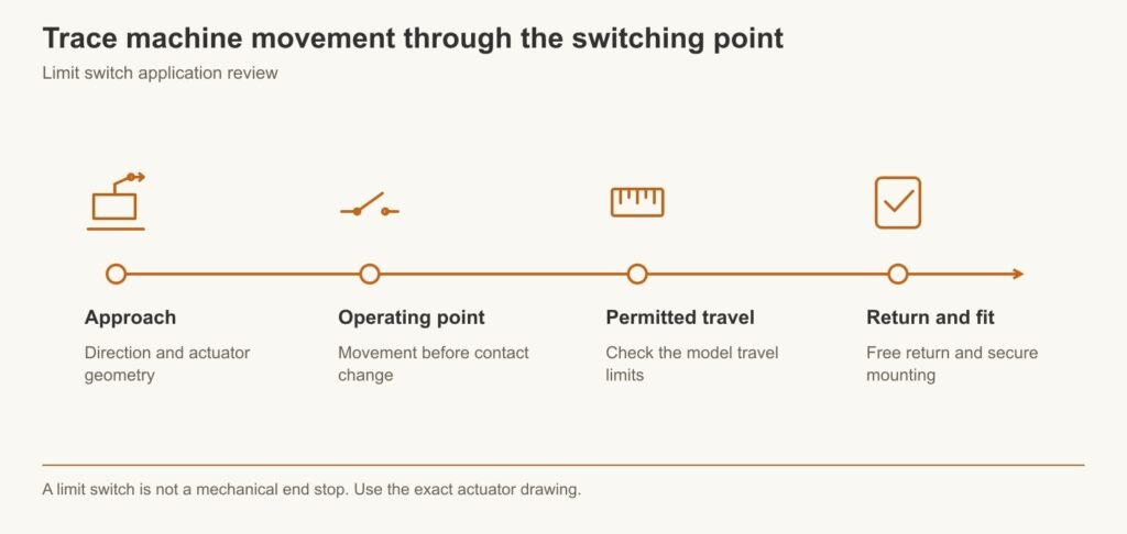
Choose a YJME-8 limit switch by matching the actuator to the machine’s approach direction, movement and mounting space. Check the operating point, permitted travel and return movement on the exact model drawing. Confirm the mechanism can operate the switch without exceeding its documented mechanical limits.
Match the YJME-8 Actuator to the Machine Movement
Define the Approach Direction and Required Switching Point
Describe the moving part before choosing the switch head. Show its approach direction, speed, available travel and the position where the signal should change. Include the return path, because the actuator must reset reliably when the mechanism moves away.
YIJIA offers the YJME-8 limit switch range. To evaluate a candidate, connect its actuator drawing to the actual machine movement. A product photograph can suggest a possible arrangement, but it cannot establish permitted direction, travel or force.
Provide a movement sketch with a fixed reference, the moving part and the intended switching location. Show the full range rather than only the instant at which the actuator is touched. Include any approach from the opposite direction, rebound or vibration that can occur during normal operation. These details help distinguish a controlled actuation from an arrangement that may strike or drag the actuator unexpectedly.
State what the position signal is used for. It might confirm that a part has reached a location or provide an ordinary sequence input. The role affects the required repeatability, response and electrical interface. If the function has safety implications, its requirements need a separate engineering assessment. A general YJME-8 selection discussion should not be treated as validation of a complete protective system.
Mechanical and Electrical Checks for YJME-8 Selection
Compare the Available Actuators for the Actual Mechanism
Compare only the actuator options confirmed for the proposed YJME-8 model. Match the contact point and movement direction to the mechanism, then check how the actuator returns. Do not assume a lever can be struck from either side or that a head can be rotated unless the model instructions permit it.
The approaching part should engage the actuator in a controlled way. An abrupt impact or sliding contact in the wrong direction can create forces that a simple end-position sketch misses. Review the whole movement, including tolerances and vibration.
Evaluate the contact geometry between the moving part and actuator. The direction of force, point of engagement and available reset movement matter throughout the stroke. An actuator that can be operated conveniently by hand may be poorly matched to the machine’s actual approach path. Use the manufacturer’s permitted actuation directions and limits for the proposed model.
Check the effect of reasonable mechanical variation. A bracket tolerance, worn guide or changed moving-part position can alter where contact occurs. The design should keep engagement within the permitted geometry across the expected conditions. If adjustment is provided, define its range and how the accepted setting is retained. This allows YIJIA to review a specific actuator requirement instead of trying to select a head from a photograph of the machine.
Distinguish Pretravel and Overtravel in the Operating Diagram
Pretravel is the movement from the free position to the operating point. Overtravel is the additional permitted movement after operation. These values describe the switch mechanism; they are not the machine’s stopping distance.
Check the manufacturer’s operating diagram and reference points. The machine may continue moving after the signal changes, so its travel must remain within the permitted actuator range under the actual conditions. A switch that works when moved slowly by hand may still be overdriven during normal operation.
Keep the operating point, reset point and permitted end of travel distinct when reading the diagram. The position at which a contact changes during approach may differ from the position at which it returns during withdrawal. Use the model’s definitions and reference points rather than assuming one switching location describes both directions.
Assess the machine movement after the signal is generated. Controller response, mechanical inertia and the drive arrangement can allow further travel. Those effects belong to the machine design and cannot be absorbed by assuming unlimited actuator overtravel. Check the worst relevant movement against the permitted range. If the remaining travel is excessive, revise the mechanism, switching location or control design before accepting the switch. A successful slow hand test cannot replace that assessment.
Check Mounting Dimensions and Actuator Clearance
Use the complete mounting drawing, including the actuator’s moving envelope. Allow access to the fixing points and electrical connection, and consider how the switching position will be adjusted and retained. A bracket that flexes can change the effective operating point even when the switch itself is repeatable.
Selection example: a carriage passes a switching position before reaching a separate mechanical stop. Review the carriage’s approach and remaining travel, then select and position a suitable actuator. The switch reports position; the mechanical arrangement must prevent the carriage from forcing the actuator beyond its limit.
For the carriage example, mark the required signal point and the separate mechanical stop on the same drawing. Show the actuator path from first engagement through the remaining carriage movement and then through release. This makes it possible to review whether the selected mounting position provides the required signal without overdriving the switch.
Consider bracket stiffness and service access together. A flexible mounting can shift the operating point, while an inaccessible adjustment can make repeat setting difficult. The fixing arrangement should preserve the accepted position under the expected conditions. Retain enough clearance to inspect the actuator and electrical connection. If a guard or adjacent component will be fitted later, include it in the access review rather than approving an installation that works only with the surrounding machine partly dismantled.
Verify Contact States and Load Conditions for the Selected Model
Identify the required normal and operated contact states and compare them with the exact diagram. Check the circuit load as well as the mechanical action. A position input to a controller and a directly switched load can create very different electrical duties.
Where a small signal is involved, minimum-load suitability matters. Where an inductive load is involved, interruption conditions matter. Do not infer an application’s safety function from the word limit or from a general industrial product description; that requires a separately specified and validated design.
Record the actual electrical load seen by the contacts. A controller input requires a reliable state at its specified voltage and current; a directly switched coil or other load requires an appropriate switching-duty review. Contact notation and actuator shape do not establish either type of suitability. Keep the electrical data tied to the complete proposed switch reference.
Define how the control system interprets the normal and actuated states. An NC path may be useful for a particular ordinary input function, but the circuit’s response to an open wire or lost supply depends on the complete design. Do not infer fault coverage from the contact choice alone. Review input filtering and timing where short engagement or vibration could affect the signal observed by the controller.
A limit switch is not a mechanical end stop. Use the exact actuator drawing.
How the Right YJME-8 Configuration Helps Machine Integration
Match the Actuator Geometry to the Available Motion
Matching the actuator to the movement can reduce unnecessary mechanical adaptation. A suitable contact point and approach direction help the designer create controlled operation with room for reset and service. The choice should come from the actual YJME-8 drawings and the machine sketch together.
Send YIJIA the mechanism information early in the enquiry. That is more useful than choosing a head by appearance and later asking the machine builder to make it work within fixed space.
A well-prepared enquiry includes both a movement sketch and a mounting sketch. The first describes the force and travel the actuator will experience; the second describes the space and fixing arrangement available. Add the required electrical function and identify which dimensions are fixed. This lets the supplier distinguish a potentially suitable actuator from one that would require an unacceptable machine modification.
For a replacement, include the existing complete reference and safely obtained photographs showing the installed orientation. Explain whether the replacement must fit the current bracket unchanged. Similar external size does not guarantee the same operating or reset points. Reviewing those points before ordering can prevent a mechanically fitting replacement from shifting the machine’s sequence or requiring unexpected adjustment during installation.
Make the Switching Point and Mounting Position Easier to Verify
For repeat builds, the record should distinguish a component dimension from an adjustable machine setting. That makes assembly and troubleshooting easier: a changed switching point can be traced to mounting, adjustment, movement or component behavior rather than treated as an unexplained electrical fault.
Use a commissioning record that separates the component identity from the machine setting. Identify the switch reference, actuator orientation, mounting position and accepted adjustment. Observe approach and return during the equipment’s approved procedure and record the point at which the intended signal changes. Where repeatability matters, assess representative repeated movement rather than relying on a single operation.
Maintenance should review the mechanism as well as the electrical symptom. A shifted bracket, worn engagement surface or changed travel can alter operation without an internal switch defect. Keeping the accepted setting and movement record helps distinguish those causes. For repeat machines, the same record provides assembly with a defined starting point and gives YIJIA a clear reference if a different candidate is proposed for the next build.
Frequently Asked Questions
Which YJME-8 Actuator Fits My Approach Direction?
The correct option is the one whose documented approach direction, movement and operating limits match the mechanism. Send a sketch showing the full path and required switching point. Have the candidate’s exact actuator and mounting drawing confirmed before ordering.
What Is the Difference Between Pretravel and Overtravel?
Pretravel occurs before the switching point; overtravel is the permitted additional movement after it. Use the model’s diagram and definitions when setting the mechanism. Neither value should be confused with the distance a machine needs to stop after receiving a signal.
Can a Limit Switch Be Used as a Mechanical End Stop?
Do not use an ordinary limit switch as the machine’s mechanical stop. The mechanism must remain within the actuator’s documented movement limits. Provide an appropriate stop or other mechanical arrangement where needed and verify that it prevents excessive switch travel.
Check My Limit Switch Application
Send the Mechanism Drawing and Movement Details with the Circuit Load
Send YIJIA the approach and return path, speed, required switching position, available travel, mounting space and circuit load. Include the existing part number for a replacement. Request the matching actuator, travel and electrical documents for the proposed YJME-8 configuration.
Search Metadata
Title: YJME-8 Limit Switch Selection
Description: Match a YJME-8 limit switch to machine movement, actuator travel, mounting space and contact duty using the exact model documents.
YIJIA switch technology guide • Technology concept illustration A metal button with a sealed face can be attractive for equipment exposed to frequent cleaning or repeated operation. Its appearance, however, says little about what happens electrically when someone presses it. A piezoelectric push button switch and a conventional mechanical button may fit similar panel openings […]
A red push button is easy to notice, but its colour does not tell you what happens inside the switch. It may provide a momentary command, hold a contact in a changed state or combine switching with illumination. Choosing the right device starts with the required control function, not the colour of its head. For […]
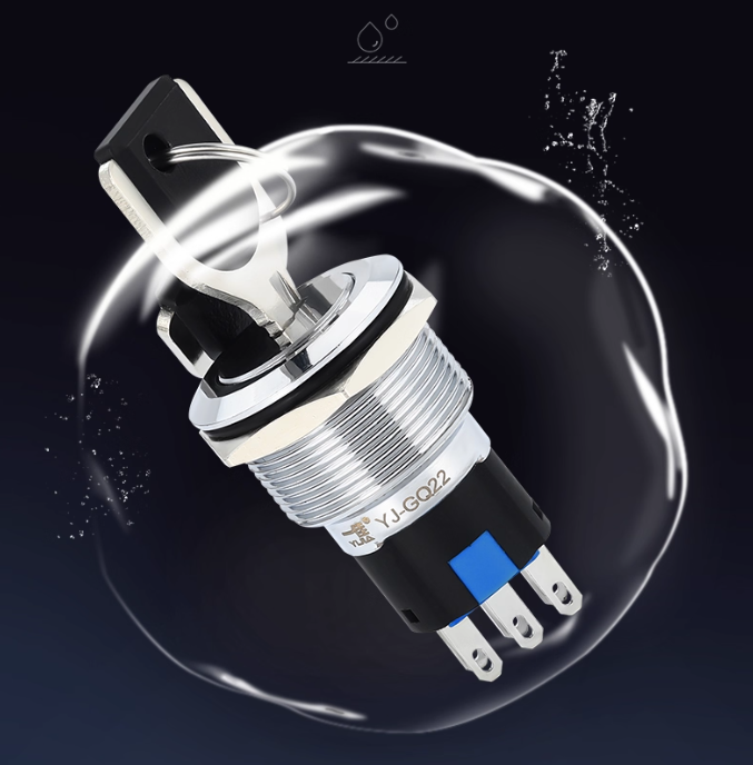
Installation dimensions: φ19MMCurrent: 5A/10A/15A/18AOperation: momentary / latching-cabinet latchIP degree: lP40 (waterproof industrial push button switch)The shell material: brass clad Chromium/stainless steel Want to know more about the product: Metal Push Button Switch In modern industrial automation and control systems, metal push button switche are widely used for their reliability and safety. As a renowned supplier […]
We use cookies to enhance your browsing experience, serve personalised ads or content, and analyse our traffic. By clicking "Accept All", you consent to our use of cookies.