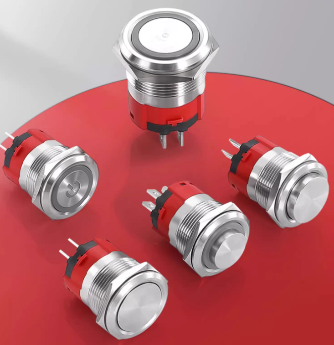
Metal Push Button Switch are integral components in a variety of electrical and industrial applications, prized for their durability, reliability, and sleek design. Whether controlling industrial machinery, automotive electronics, or household appliances, ensuring safe and proper electrical connections for these switches is paramount.
Have you ever wondered what risks you might face if a metal push button switch is wired incorrectly? Electrical hazards like short circuits, overloads, or even electric shocks can arise from improper handling. This blog aims to guide you through the critical electrical safety considerations when connecting metal push button switches. Ready to deepen your understanding and secure your connections? Let’s dive in!

Basic Structure and Working Principle of Metal Push Button Switc
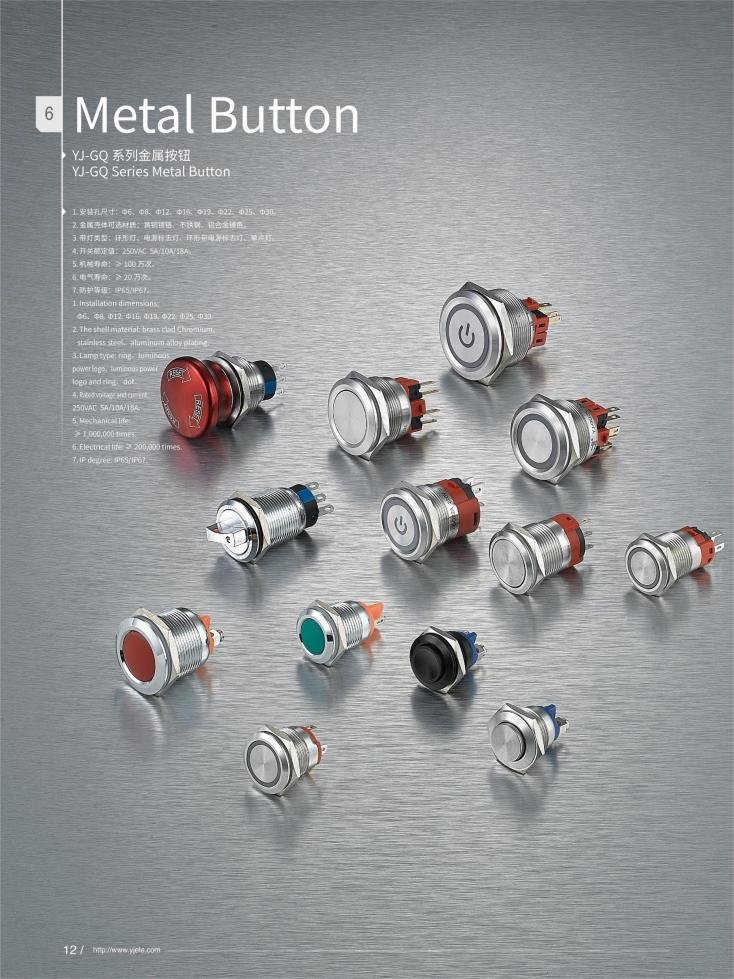
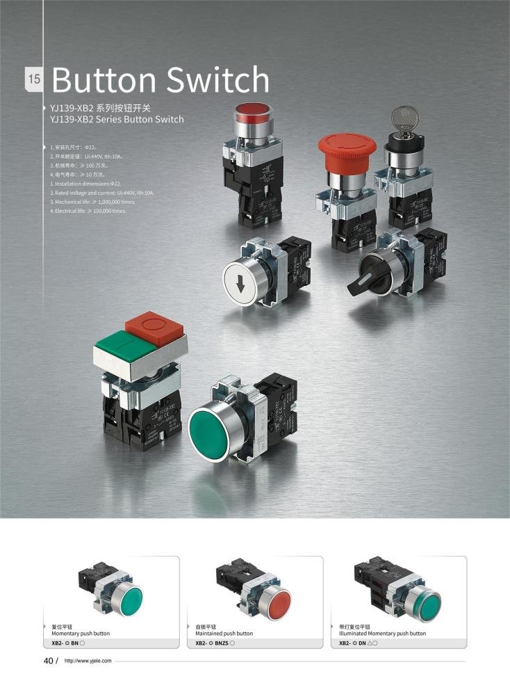
At its core, a metal push button switch consists of a robust metal shell and metal contacts inside, typically made from conductive materials like silver alloys. This construction makes them highly durable, wear-resistant, and corrosion-resistant — a perfect match for harsh industrial environments.
How It Works
- Pressing the Button: When you press the button, the internal metal contacts either come together or separate, completing or breaking the circuit.
- Contact Types: Usually, these switches feature Normally Open (NO), Normally Closed (NC), and Common (COM) terminals, which define how the switch interacts in the circuit.
| Feature | Description |
|---|---|
| Metal Shell | Durable and corrosion-resistant stainless steel |
| Contacts | Conductive metals (e.g., silver alloy) for reliable conduction |
| Terminal Types | NO, NC, and COM for various circuit control needs |
| Button Types | Momentary (self-resetting) and latching (self-locking) |
Knowing these basics will help you select and wire switches that suit your application while maintaining safety. If you’re curious about the mechanical sides and materials, these details matter as much as electrical specs.
Key Electrical Safety Considerations in Wiring Metal Push Button Switch
Improper wiring is a common cause of electrical mishaps. Here’s a detailed checklist to keep your wiring safe and sound:
Voltage and Current Ratings
Always check the rated voltage and current of your switch. Matching these specs with your system requirements prevents damage and hazards.
| Parameter | Recommendation |
|---|---|
| Voltage Rating | Should meet or exceed system voltage (e.g., 12V, 24V, 110V) |
| Current Rating | Handles load current comfortably (e.g., 5A, 10A, 18A) |
Wiring & Connection Methods
- Proper Wire Gauge: Choose wires thick enough to avoid overheating and voltage drops.
- Terminal Connections: Use correct terminals (NO, NC, COM) per wiring diagrams.
- Securing Wires: Tighten terminal screws firmly; if soldering, ensure strong, clean joints.
- Insulation: Avoid exposed wiring; cover connections with heat shrink tubing or electrical tape.
Prevent Common Issues:
- Avoid mixing positive and neutral wires incorrectly.
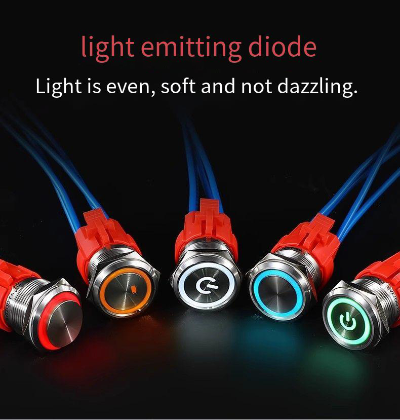
- Double-check polarity especially for illuminated switches with LEDs.
- Use switches with appropriate IP ratings (e.g., IP65 or IP67) in dusty or wet environments.
By taking these steps, you not only protect the circuits but also improve longevity and reliability.
Thinking about upgrading your control panels? Reach out to explore our certified metal push button switches that ensure safe and efficient operation.
Importance of Safety Standards and Certifications
Selecting switches compliant with recognized safety standards is non-negotiable to ensure operational safety and legal compliance.
| Standard/Certification | Significance |
|---|---|
| CE | Product safety compliance in Europe |
| RoHS | Restriction on hazardous substances |
| GB/T 14048.5 | Chinese national standard for low-voltage switchgear and controlgear |
Choosing certified switches helps avoid risks such as electrical shock, overheating, or fire hazards — especially crucial for industrial clients with strict inspection regulations.
Free consultation, huge price discounts!
If you have more specific questions or need help choosing the right switch!
Common Electrical Hazards and How to Prevent Them
Electrical safety is about anticipating risks and designing systems to eliminate or manage them. These common hazards deserve your attention:
1️⃣Electric Shock
- Always disconnect power before wiring.
- Use switches with good insulation and protective housings.
- Wear insulated gloves where applicable.
2️⃣Overcurrent and Short Circuit
- Ensure the switch’s current rating matches the application.
- Incorporate appropriate fuses or circuit breakers upstream.
- Regularly inspect wiring for wear or damage.
3️⃣Mechanical Damage Leading to Electrical Faults
- Avoid excessive force while pressing or installing switches.
- Install switches securely to prevent looseness that compromises contacts.
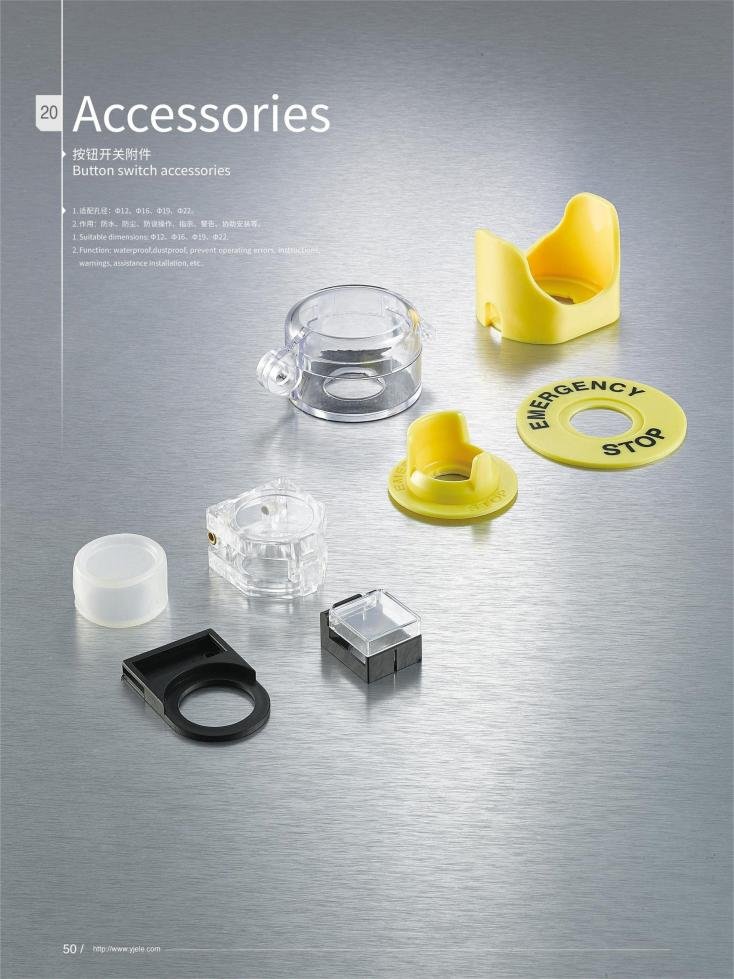
Emergency Stop Switches Safety
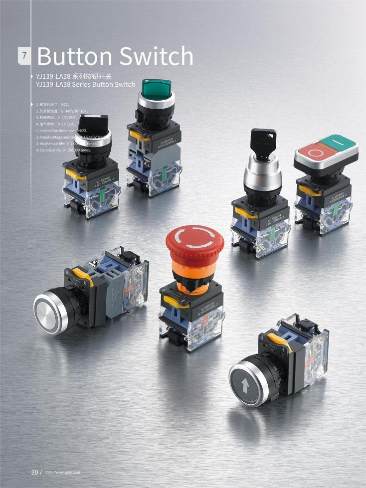
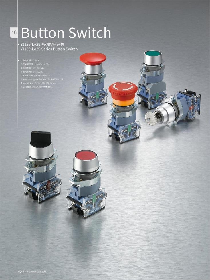
Emergency stop (E-stop) buttons, often red mushroom-head types, usually use Normally Closed (NC) contacts for fail-safe operation. Proper wiring here is a matter of life and death:
| Property | Note |
|---|---|
| Contact Type | Use NC for immediate circuit disconnection |
| Redundancy | Dual-channel wiring recommended for critical machines |
| Regular Testing | Verify the reset and function periodically |
Wiring Considerations for Different Types of Metal Push Button Switch
Not all metal buttons are wired the same. Here’s what you need to keep in mind:
Self-Reset (Momentary) vs. Self-Locking (Latching)❗
| Switch Type | Wiring/Operation | Typical Use Cases |
|---|---|---|
| Self-Reset | Circuit closed only while pressed | Start/Stop buttons |
| Self-Locking | Press once to latch on, press again to release | Power switches, Mode selectors |
Illuminated Switches❗
- LEDs inside these switches require correct polarity wiring.
- They often support different voltages for the illumination circuit, separate from the switching circuit.
- Pay attention to LED wiring instructions; polarity reversal might damage the light.
Waterproof and Explosion-Proof Switches❗
- Ensure seals and gaskets are intact during installation.
- Use switches certified for hazardous environments to prevent sparks or moisture ingress.
Looking for specialized metal push button switches? Contact us for tailored solutions meeting industrial standards.

Practical Installation and Maintenance Tips Metal Push Button Switch
Successful installations combine preparation, precise execution, and ongoing care.
Metal Push Button Switch Installation Steps
- Panel Preparation: Drill correct-sized holes corresponding to switch diameters (e.g., 12mm, 16mm, 19mm).
- Mounting: Insert switch, secure with locknut ensuring watertight gasket seals.
- Wiring: Connect wires firmly to correct terminals; solder if necessary.
- Testing: Check switch functionality and LED illumination before powering up the full system.
Maintenance Recommendations
- Inspect seals and contacts biannually.
- Keep the surface clean using alcohol-free wipes.
- Replace worn-out switches promptly to avoid electrical hazards.
A well-maintained switch ensures both safety and longevity, saving downtime and repair costs.
Connecting metal push button switch safely is vital for preventing electrical hazards and ensuring reliable system operation. By understanding the switch’s structure, respecting voltage/current ratings, adhering to wiring best practices, and selecting certified components, you create a safer environment for equipment and users alike.
Remember, proper installation and regular maintenance extend the life of your switches and secure your operations. If you want to avoid costly downtime or dangerous malfunctions, choosing high-quality metal push button switches with the right certifications and following these safety tips is the way forward.
Want to discuss your next project or need tailored solutions? Contact us for certified metal push button switches and expert advice — your safety and satisfaction are our priority!
FAQ
Most switches label terminals as NO, NC, and COM. Refer to manufacturer documentation or markings on the switch body for clarity.
1. Loose connections causing intermittent operation.
2. LED indicator failure due to polarity errors.
3. Contact wear leading to circuit open or short.
Always connect LED wires observing polarity; check LED voltage ratings and use series resistors if required to prevent burnout.
Self-locking switches maintain contact state after pressing, requiring wiring that supports toggling functionality, unlike momentary switches that only close contact while pressed.
Verify gasket condition, utilize rated IP65/IP67 switches, and confirm panel seals during installation.
Use normally closed contacts wired to cut power instantly. Test regularly for proper reset.
Use a multimeter continuity test between terminals with the button pressed and released.
Inspect wiring, tightness of terminals, and switch mechanical state. Replace if contacts are damaged.