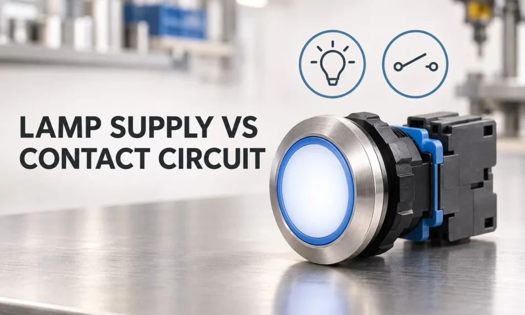
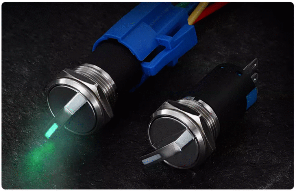
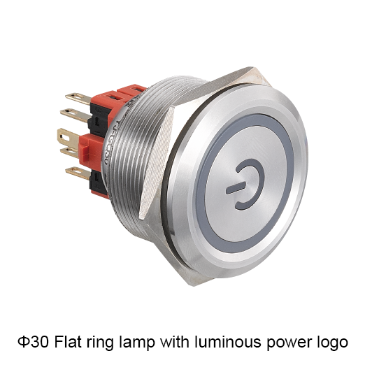
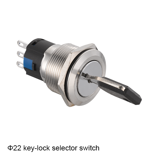
An illuminated push button contains two functions at one panel position: an operator changes electrical contacts, while a lamp provides visual information. These functions may be physically integrated, but they should not be treated as one electrical specification.
YIJIA’s LA36A product page lists lamp voltage options separately from the switch rating table. This separation is the key procurement lesson: the supply for the LED and the electrical duty of the contacts must each be confirmed.
Define What the Light Means
Before choosing a lamp voltage, decide what the illumination communicates. It may indicate that power is available, a machine is running, a command has been accepted or a fault condition exists.
The meaning determines when the lamp should energize and which circuit should control it. A light that follows the button’s physical position is not always the same as a light that reports the machine’s actual state.
Write the required behavior in plain language before drawing the circuit. For example: “The ring illuminates only after the controller confirms that the motor is running.” This is more useful than simply requesting a green illuminated button.
Confirm the Lamp Supply
The LA36A page lists multiple AC/DC and AC lamp voltage options. The requested voltage should match the actual control power available in the panel and the selected product configuration.
Ask the supplier to confirm:
Rated lamp voltage.
AC, DC or AC/DC designation.
Lamp terminal identification.
Whether polarity matters for the selected version.
The complete model number that includes the lamp option.
Do not infer the lamp voltage from the switch contact rating. A contact may be suitable for one electrical duty while the integrated lamp requires a different supply.
Specify the Contact Circuit Separately
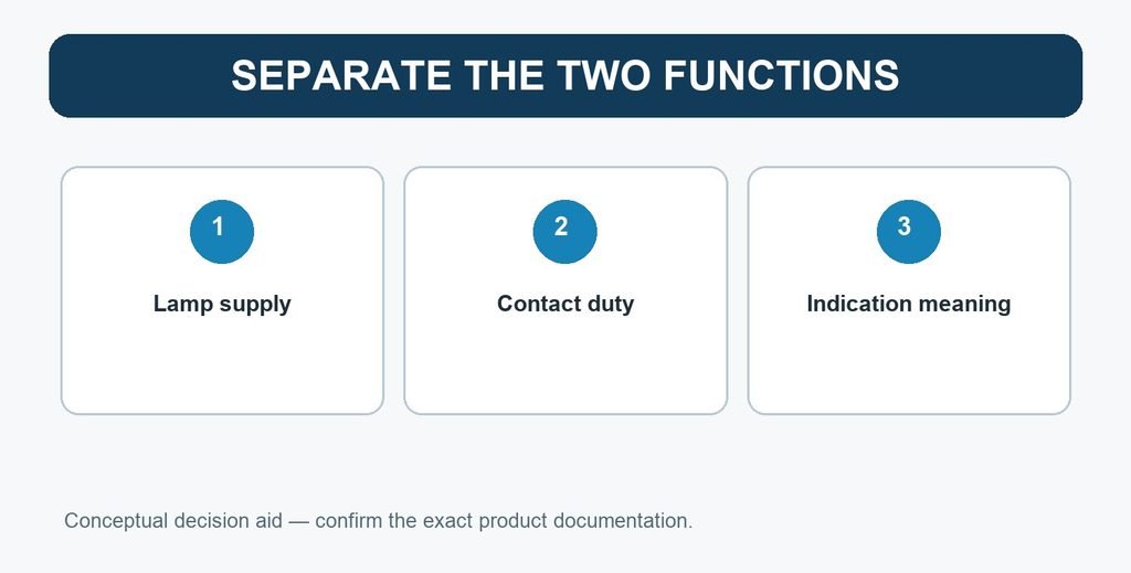
The switch contacts control another circuit. Their suitability depends on voltage, current, AC or DC operation and load type. The LA36A page provides separate ratings for different conditions, including resistive and inductive loads.
Conceptual decision flow; confirm the exact model documentation.
The buyer should state what each contact switches. A PLC input, relay coil and directly connected load are not equivalent duties. If two contacts are installed, list the purpose of each one.
This creates two clear specification blocks:
Function
Information Required
Lamp
Supply type, rated voltage, color and intended meaning
Contacts
NO/NC arrangement, operating voltage, current and load type
Check the Terminal Diagram
Illuminated versions require a diagram that distinguishes lamp terminals from switching contacts. Use the drawing for the exact model, not a generic internet diagram.
Before approving the product, verify:
Lamp terminals are clearly identified.
NO and NC contacts are identified separately.
The selected lamp voltage appears in the complete model description.
The panel drawing reflects how the indication is controlled.
The rear assembly fits the available panel depth.
The LA36A model table is explanatory, and the product page warns that some theoretical combinations may not be actual available products. Supplier confirmation is therefore part of the selection process.
Avoid Common Ordering Errors
Common errors include specifying only the panel control voltage, assuming the LED shares the contact circuit, omitting the desired indication color or requesting an illuminated head without defining when it should light.
Another mistake is to use the lamp as proof that the controlled equipment is operating. A lamp connected directly to the button circuit may show that a command was issued, not that the machine completed the action. The control designer must decide which signal should drive the indication.
Choose the Indication Source Deliberately
An illuminated operator can be wired in several conceptual ways, and the correct choice depends on what the operator needs to know. The lamp may be controlled by the same command circuit, by a controller output or by feedback from another device. These arrangements do not communicate the same information.
If the light energizes with the command, it shows that the command path is active. If it is driven by confirmed feedback, it may represent an achieved machine state. The article cannot define the correct circuit for every machine, but the purchasing specification should state the intended meaning so the electrical designer and supplier review the same requirement.
Use clear wording such as “lamp indicates command active” or “lamp indicates confirmed equipment running.” Avoid a vague phrase such as “lighted when on” unless the term “on” is defined for that machine.
Review Color with the Function
Color is part of the indication, not a decorative choice. The selected color should follow the project’s control philosophy, target market requirements and equipment documentation. The LA36A product information shows that lamp color is a configurable feature, but the meaning assigned to that color comes from the equipment design.
Record the color together with the state it represents. When several illuminated controls appear on one panel, check that the set remains understandable rather than selecting each button independently. If a project standard or safety requirement applies, use the current authoritative source during the equipment review.
Do not claim that one color has a universal meaning in every country or application. A useful article guides the buyer to document the intended meaning and verify the applicable rules.
Check Panel Power and Voltage Variation
The nominal lamp voltage should be selected from the actual control supply. Also identify whether the supply is AC, DC or AC/DC as stated for the proposed product. A nominal value alone may be incomplete if the selected version is supply-specific.
Review the equipment’s expected supply range with the selected product information. Do not assume that a lamp will tolerate any fluctuation around the nominal value. If the panel uses more than one control voltage, mark the lamp circuit clearly in the schematic and on the relevant terminal information.
For replacement work, verify the existing supply rather than copying the voltage from an old label without checking the circuit. Previous modifications, external modules or wiring changes can make a visual replacement unsafe or ineffective.
Treat the Lamp as Part of the Complete Model
The lamp option affects the complete ordering code and rear connection. It should remain attached to the operator specification throughout quotation, sample approval and repeat purchasing.
A useful approval record includes the operator type, contact arrangement, lamp color, lamp supply, terminal diagram and complete model code. If the supplier changes any of these items, compare the revised configuration with the panel drawing.
The LA36A page notes that the model explanation includes combinations that may not be actual products. This means a code assembled from individual options still needs supplier confirmation. Do not approve a purchase solely because every element appears separately in the code table.
Prepare the Panel Drawing for Maintenance
The schematic should show the lamp separately from the switching contacts. Add the lamp supply and terminal references, and describe the signal that controls it. This helps maintenance staff distinguish a failed lamp, a missing supply and a control-logic condition.
Where the lamp and contacts are on different circuits, make the separation visible in the documentation. A technician should not need to infer the lamp voltage from the contact wiring. Consistent wire numbers and terminal labels also make later replacement easier.
If an illuminated operator is replaced with a non-illuminated version, or vice versa, treat the change as more than a cosmetic substitution. The wiring, bill of materials and operator information may all need revision.
Verify the Indication During Commissioning
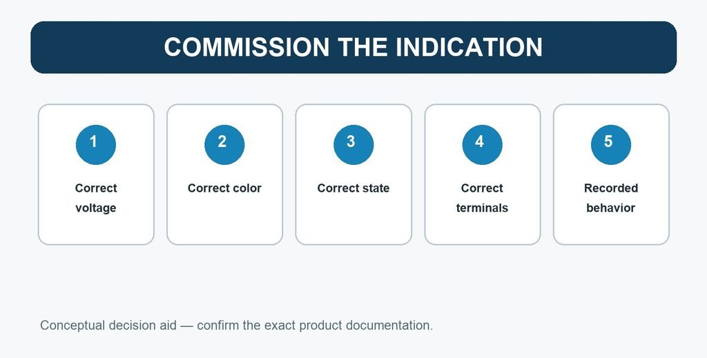
Commissioning should test the information conveyed by the lamp, not only whether the LED can illuminate. Operate the machine through the relevant states and compare the lamp with the expected command or feedback signal.
Check for reversed logic, a lamp that remains energized in the wrong state and a color that conflicts with the panel legend. If the indication depends on controller logic, verify the programmed output and the field wiring together. If it depends on equipment feedback, confirm that the feedback device represents the intended state.
Record the accepted behavior in the machine test or inspection documentation. This gives later maintenance teams a reference for distinguishing a failed lamp from an incorrect command, missing feedback or control-logic issue.
For repeat builds, keep the approved lamp supply and indication meaning with the product code. A substitute illuminated operator should not be accepted until its voltage, color, terminals and complete behavior have been compared with that record.
Conceptual procurement checklist; not a product test or installation drawing.
FAQ
Is the LA36 LED voltage the same as the contact voltage?
Not automatically. The LA36A product page lists lamp voltage and switch ratings separately. Specify both.
Can the lamp and contacts use the same power supply?
That depends on the selected model and circuit design. Confirm the lamp specification, contact duty and wiring diagram.
Does an illuminated button prove that the machine is running?
Only if the control circuit is designed to use a confirmed machine-status signal. Illumination connected to a command circuit may indicate only that the command circuit is energized.
Are all listed lamp voltages available with every operator type?
The product page states that not every model-code combination represents an actual product. Confirm the complete configuration with YIJIA.
Discuss Your Requirements
Send the required operator type, lamp meaning, lamp supply, color, contact arrangement, contact load and quantity. YIJIA can then confirm an available illuminated LA36 configuration and its terminal information.
Installation dimensions: φ19MMCurrent: 5A/10A/15A/18AOperation: momentary / latching-cabinet latchIP degree: lP40 (waterproof industrial push button switch)The shell material: brass clad Chromium/stainless steel Want to know more about the product: Metal Push Button Switch In modern industrial automation and control systems, metal push button switche are widely used for their reliability and safety. As a renowned supplier […]
Installation dimensions: φ16MMCurrent: 5A/10A/15A/18AOperation: momentary / latching-cabinet latchIP degree: lP40 (waterproof industrial push button switch)The shell material: brass clad Chromium/stainless steel Want to know more about the product: Metal Push Button Switch Metal button switch LED indicator light power on effect diagram. LED lights are available in red, green, blue, yellow, and white for selection. […]
Metal push button switch are essential components in modern electronic and industrial devices. Whether it’s powering a machine, operating a control panel, or activating a safety system, these switches provide durability, reliability, and precision control. In this blog, we will explore two main types: momentary metal push button switches and latching metal push button switches. Understanding their differences […]
We use cookies to enhance your browsing experience, serve personalised ads or content, and analyse our traffic. By clicking "Accept All", you consent to our use of cookies.