When you hear people talk about a relay switch AC, they are usually talking about an electrically controlled switch that turns AC loads on and off using a small control signal. For B2B buyers, OEMs, and electrical engineers, understanding how this AC relay switch works is the key to choosing the right component, preventing failures, and reducing maintenance cost in the field.
What Is a Relay Switch for AC?
A relay switches for AC is an electrically operated device that uses an electromagnetic coil or solid‑state elements to open and close contacts in an AC circuit. In simple terms, a low‑power control signal (often from a PLC, thermostat, or control board) safely switches a much higher AC voltage and current going to the load.
In industrial control panels, HVAC units, motor starters, and building automation systems, AC relay switches play the role of an isolated “gatekeeper” between sensitive electronics and high‑power equipment. This isolation helps protect control boards and allows one controller to operate multiple AC loads such as compressors, pumps, fans, and heaters.

Typical AC Relay Switch Components
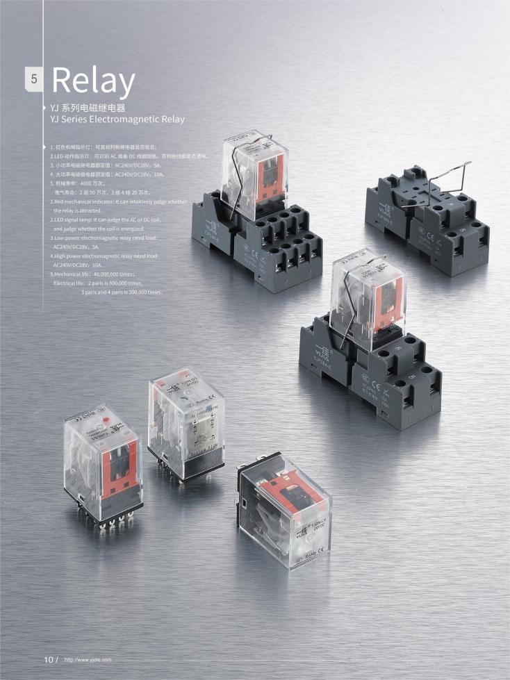
An electromechanical relay switch AC generally includes these elements:
- Coil (AC or DC control voltage)
- Movable armature
- Return spring
- Fixed and movable contacts (NO/NC)
- Terminals for coil and contacts
Solid‑state AC relay switches remove moving parts and use devices such as TRIACs or thyristors to perform the switching function. These SSRs are common where silent operation, high life expectancy, and fast switching are important, such as in temperature controllers and PLC‑based process control.
Basic Structure Overview (Table)
Working Principle of Relay Switch AC
At the heart of the relay switch AC is electromagnetism: a small electrical input creates a magnetic field that mechanically changes the state of the contacts. This allows a low‑power side (control circuit) to safely control a high‑power side (AC load circuit) without direct electrical connection.
Step‑by‑Step: Electromechanical Relay Switch AC
Control signal applied to coil
A PLC output, thermostat, microcontroller, or manual switch applies voltage to the relay coil. For AC loads, the coil may be driven by DC (through a transistor) or directly by AC, depending on the relay design.
Magnetic field and armature motion
Current through the coil generates a magnetic field that attracts the armature and overcomes the return spring. This mechanical motion changes the position of the contacts from their normal state: NO contacts close, and NC contacts open.
AC circuit opens or closes
When contacts close, the relay completes the AC circuit, supplying power to the load such as a motor, solenoid valve, or HVAC compressor. When the coil is de‑energized, the magnetic field collapses, the spring returns the armature, and the AC circuit is interrupted.
Electrical isolation
The coil and contact circuits are galvanically isolated, which protects the control side from high voltages and fault currents on the AC line. This isolation is one of the main reasons B2B buyers prefer relay switch AC solutions over direct driving by the controller.
Solid‑State Relay Switch AC Principle
A solid‑state relay switch AC (SSR) replaces the coil and contacts with optocouplers and power semiconductors.
The control signal drives an LED inside the SSR, which activates a photodetector and gate driver on the output side.
A TRIAC, SCR pair, or similar device switches the AC load, often at the AC zero‑cross point to minimize electrical noise.
Because no mechanical contacts move, SSRs provide silent operation, faster response, and very high switching life, but may require heat sinking and careful thermal design.
Key Applications of Relay Switch AC in B2B Projects
Relay switch AC products appear in almost every corner of industrial and commercial electrical systems. For procurement and engineering teams, the main interest lies in where these components add value and which technical parameters matter in each scenario.
HVAC and Air Conditioning Systems
In HVAC systems, a relay switch AC often interfaces between the thermostat and high‑power components. Typical functions include:
- Switching the compressor clutch or scroll compressor in residential and light commercial air conditioning.
- Controlling condenser fan motors, blower motors, and electric heating strips based on low‑voltage thermostat commands.
- Integrating with defrost circuits and safety interlocks in heat pumps and rooftop units.
HVAC switching relays are widely sold as standard modules with specific coil voltages (often 24 V) and contact ratings optimized for compressor and fan loads. For B2B buyers, availability, coil voltage compatibility, and local support can be as important as the pure electrical specs.
Motor Control, Pumps, and Industrial Automation
In industrial automation, relay switch AC modules control three‑phase or single‑phase motors, pumps, conveyors, and agitators. Typical use cases include:
- Motor start/stop control from PLC outputs or low‑voltage push buttons using NO power contacts.
- Alternating between main and backup pumps through SPDT/SPDT relay configurations.
- Switching heating elements, ovens, and dryers with solid‑state AC relays for better lifetime at high cycling rates.
Large OEMs often integrate relay switch AC boards inside machine enclosures, where ambient temperature, shock, and vibration must be considered at the design stage.
Building Automation and Lighting Control
Relay switch AC devices are widely used in smart building systems for lighting, shutters, and power distribution. Building management systems (BMS) use modular relays to:
- Switch lighting circuits in offices, warehouses, and production halls.
- Control socket power, signage, and façade lighting according to schedules or occupancy sensors.
- Integrate fire alarm and emergency systems, where NC contacts are often used in fail‑safe circuits.
For projects with hundreds or thousands of channels, relay life, contact material, and socket design become critical for long‑term reliability.
Application–Parameter Snapshot
How to Choose a Relay Switch AC for Your Project
From a purchasing and engineering perspective, choosing the right relay switch AC is all about balancing electrical performance, lifetime, and total cost of ownership. Below are the main factors your technical and sourcing teams should check together when selecting components for HVAC, automation, or panel‑building projects.
Electrical Ratings and Contact Configuration
The first step is matching the relay’s ratings and contact configuration to the AC load. Main points:
- Coil voltage and type: Verify coil voltage (e.g., 12 VDC, 24 VDC, 24 VAC, 110 VAC) and whether the control side of your system can supply it reliably.
- Contact voltage and current rating: Confirm that the relay contacts are rated for the AC mains voltage and load current, including starting current for motors and compressors.
- Contact form (NO/NC, SPST, SPDT, DPDT): Choose configurations that match your control logic, redundancy, and safety requirements.
Under‑sizing contact ratings is one of the main reasons for premature relay failures in the field, especially in inductive loads like motors and transformers.
Mechanical vs Solid‑State Relay Switch AC
Both electromechanical and solid‑state AC relay switches have distinct benefits.
Electromechanical relay switch AC:
- Clear contact separation, low leakage current, and visible contact state.
- Cost‑effective for moderate switching frequencies and general HVAC or industrial loads.
Solid‑state relay switch AC:
- No mechanical wear, high switching speed, and silent operation.
- Excellent for high‑frequency switching, heating control, and sensitive environments where contact bounce and noise must be minimized.
Many OEMs use a mix of both technologies in one system, with electromechanical relays for main power and SSRs for fast or precise control tasks.
Installation, Environment, and Standards
Practical details also affect your choice of relay switch AC in real projects. Consider:
- Mounting style (plug‑in, DIN rail, PCB, panel mount) and the available space in your control cabinet.
- Ambient temperature, humidity, vibration, and enclosure rating (IP) in the final installation.
- Required standards and certifications (UL, CE, CCC, etc.) for the target market and industry.
A disciplined pre‑purchase checklist can reduce redesigns and field returns. If you would like, you can send basic project parameters (load type, current, voltage, environment), and a tailored relay switch AC selection can be suggested—along with a formal quotation.
Selection Criteria Overview
If your team is currently designing or upgrading systems that need reliable relay switch AC solutions, you are welcome to send specifications or RFQs at any time so the most suitable products and pricing can be prepared for your application.
FAQ
A relay switch AC is usually smaller and used for lower to medium power loads, while a contactor is designed for higher current motors and heavy industrial loads with specific utilization category ratings.
Yes, many relay switch AC products use a DC coil controlled by a PLC or microcontroller, while the contacts switch an AC load, providing both control flexibility and galvanic isolation.
A failed relay switch AC or HVAC switching relay can prevent power from reaching the compressor or fan, even if the thermostat sends the correct signal.
Check the full‑load current, starting current, and voltage of the motor, then choose a relay with a contact rating and HP rating comfortably above these values, considering inductive load categories.
Use a solid‑state relay when you need frequent on/off cycles, silent operation, or reduced electrical noise, for example in precise temperature control or fast process control loops.