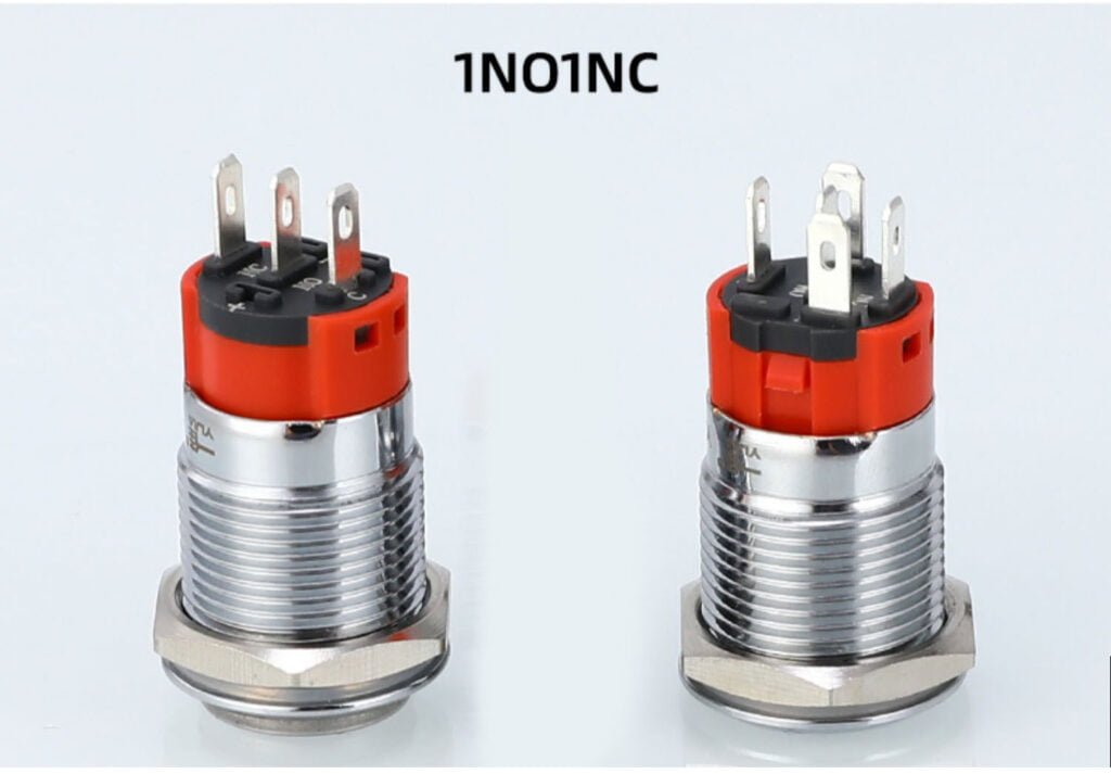
1. Determine the terminals: Most limit switches have three terminals: Normally Open (NO), Normally Closed (NC), and Common (COM). Before wiring, confirm the terminal markings of the switch.
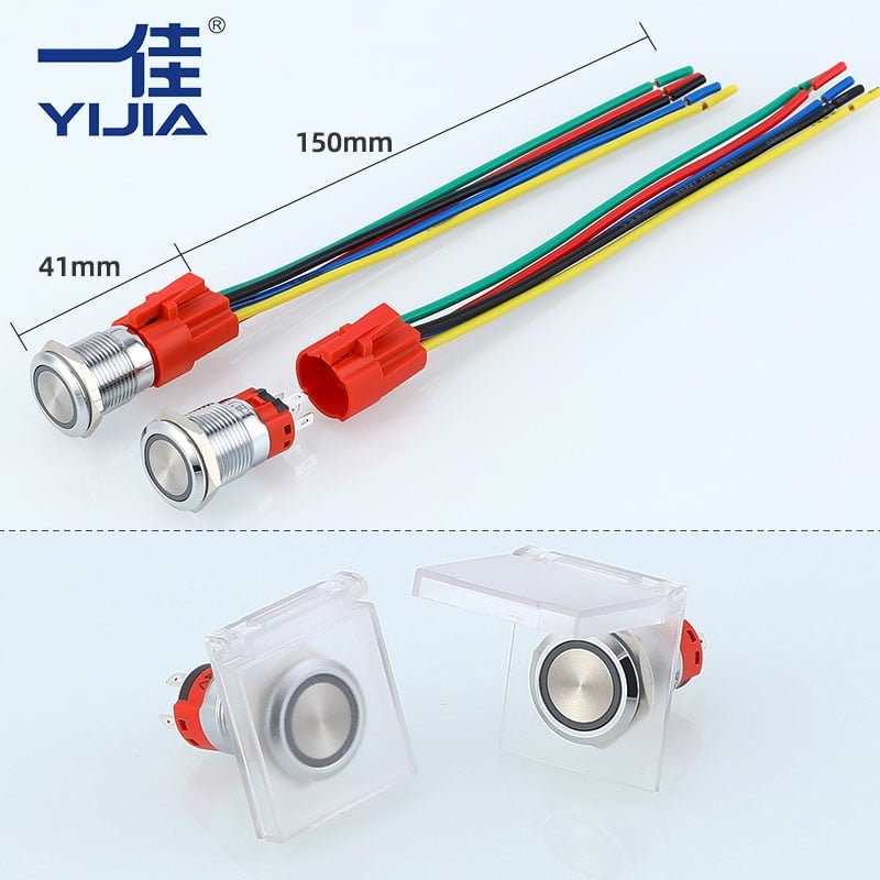
2. Select the appropriate cable: Select a cable of appropriate specifications based on the voltage and current requirements of the device. Make sure the cable is long enough and can withstand the temperature and wear in the working environment.
3. Power-off operation: Before wiring, make sure the device is completely powered off to avoid the risk of electric shock.
4. Connect the Common (COM): Connect the power line or control line to the Common (COM) of the limit switch.
5. Connect the Normally Open (NO) or Normally Closed (NC):
- If you need to open the circuit when the limit switch is triggered, connect to the Normally Closed (NC).
- If you need to close the circuit when the limit switch is triggered, connect to the Normally Open (NO).
6. Fix the wiring: Use cable clamps or other fixing devices to fix the cable in place to prevent the cable from loosening or being damaged.
7. Check the connection: Carefully check all connection points to ensure that the wiring is secure and correct.
8. Power-on test: Restore power to the equipment and perform a functional test to ensure that the limit switch works properly when triggered.
1. Mechanical action: The limit switch is usually installed on the moving part of the equipment. When the moving part reaches the predetermined position, the mechanical action of the limit switch is triggered. This action is usually achieved by a mechanical device such as a lever, button or roller.
2. Electrical contact conversion: When the limit switch is triggered, the electrical contacts inside it will be converted. There are two ways to convert the contacts:
- Normally open (NO) contacts: In the normal state, they are open. When the limit switch is triggered, the contacts are closed and the circuit is connected.
- Normally closed (NC) contacts: In the normal state, they are closed. When the limit switch is triggered, the contacts are open and the circuit is disconnected.
3. Signal transmission: The conversion of the limit switch contacts changes the circuit state, thereby transmitting a signal to the control system or drive device. For example, when the normally open contact is closed, a signal can be sent to start the next operation, or when the normally closed contact is open, a signal can be sent to stop the operation of the equipment.
4. Feedback and control: After the control system receives the signal from the limit switch, it will perform the corresponding operation. This may include stopping the motor, changing direction, starting an alarm or other control actions. In this way, the limit switch can provide accurate feedback of the equipment position and realize automatic control and protection of the equipment.
5. Safety guarantee: The connection principle of the limit switch also involves the safety protection function. When the equipment reaches a dangerous position or abnormal state, the limit switch can automatically cut off the power supply or sound an alarm to prevent equipment damage or personal injury.
1. What is a limit switch?
A limit switch is a switch used to detect mechanical position and travel. It controls the opening and closing of the circuit by triggering the mechanical parts of the switch to achieve automatic control and protection of the equipment.
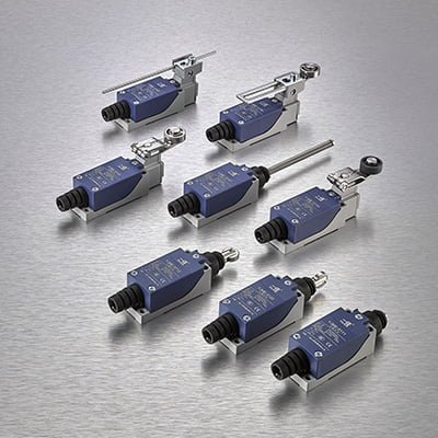
2. What are the common types of limit switches?
Common types of limit switches include micro limit switches, roller lever limit switches, button limit switches, and rotary limit switches.
3. What are the main applications of limit switches?
Limit switches are widely used in industrial automation equipment, lifting machinery, conveyor systems, door and window controls, household appliances, and other occasions that require position detection and travel control.
4. How to choose a suitable limit switch?
The following factors need to be considered when selecting a limit switch: operating voltage and current, environmental conditions (such as temperature, humidity, dust, etc.), mechanical strength, response speed, and contact form (NO/NC).
5. How to wire a limit switch?
When wiring, determine the wiring terminals (COM, NO, NC), select the appropriate cable, and ensure power-off operation. Connect the power line or control line to the corresponding terminal, and perform a functional test after fixing the wiring.
6. What are the common connection methods of limit switches?
Common connection methods include single-pole single throw (SPST), single-pole double throw (SPDT), double-pole double throw (DPDT), parallel, series and jumper connections.
7. What do the NO and NC of the limit switch contacts mean?
NO (Normally Open) means normally open contacts. The contacts are open in the normal state and closed when the switch is triggered. NC (Normally Closed) means normally closed contacts. The contacts are closed in the normal state and open when the switch is triggered.
8. What should be paid attention to when using limit switches?
It is necessary to ensure power-off operation, select appropriate switches and cables, fix wiring, avoid short circuits, conduct regular inspections and maintenance, take protective measures, refer to manufacturer guidance and perform functional tests.
9. What are the common causes of limit switch failure?
Common failure causes include mechanical wear, oxidation or ablation of electrical contacts, environmental factors (such as moisture, dust), and loose or broken wiring.
10. How to extend the service life of limit switches?
Regular inspection and maintenance, select durable and environmentally adaptable limit switches, ensure correct wiring and fixing, use protective measures such as protective covers, and avoid overloading and frequent operation.