When working with metal push button switch, understanding the function of their wiring terminals is key to ensuring correct installation and reliable operation. Whether you’re an engineer specifying switches for a new product or a technician installing control panels, you may have asked yourself: How can I quickly and correctly identify what each terminal on my metal push button switch does?
We’ll cover the basics of metal push button switches, explain the common terminal types and their markings, and share practical tips for testing terminal functions using simple tools. Along the way, we’ll integrate relevant keywords like Metal Push Button Switch and related long-tail terms that help clarify the wiring process for you and improve the article’s discoverability.
What Is a Metal Push Button Switch?
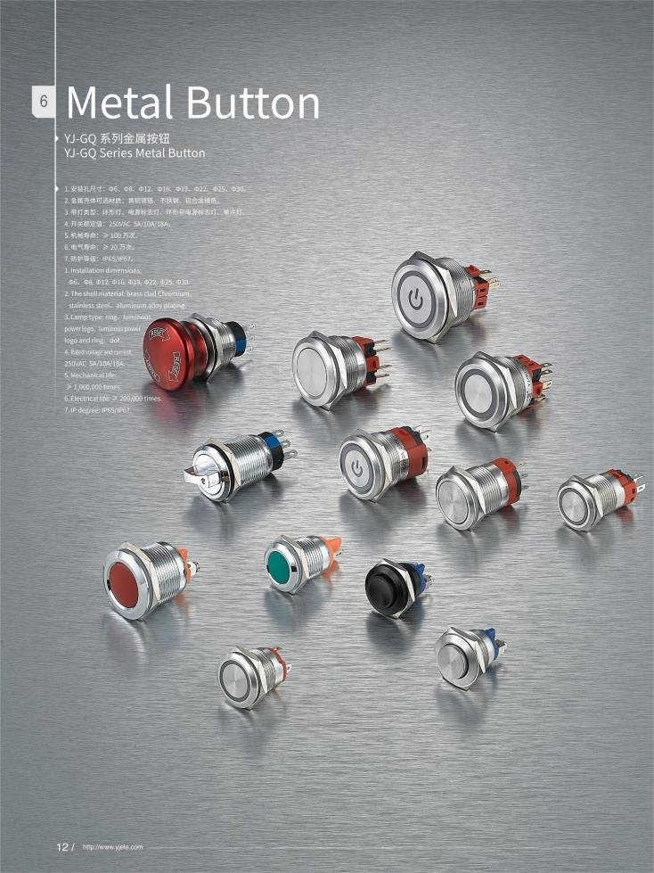
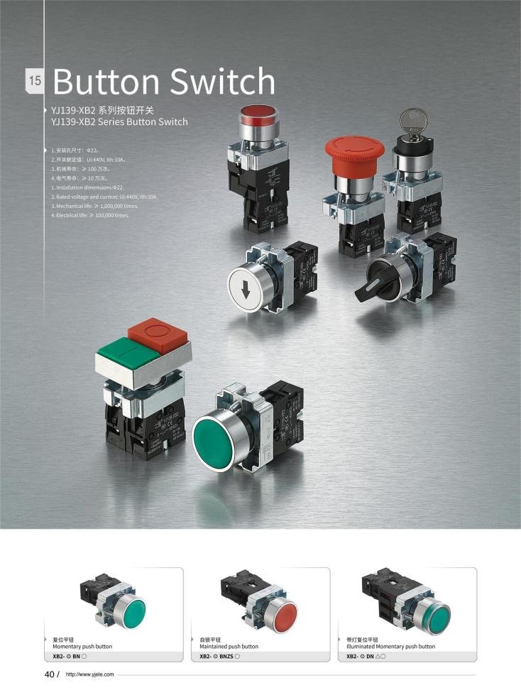
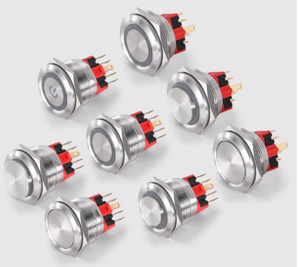
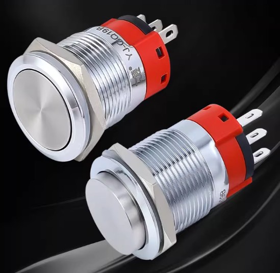
A metal push button switch YJ-GQ25B is a durable electromechanical device used to manually open or close a circuit by pressing a button. Its robust metal construction offers superior wear resistance and aesthetic appeal, making it popular in industrial machinery, control panels, and consumer electronics.
| Component | Description |
|---|---|
| Shell & Actuator | Metal and plastic parts protecting the internal mechanism |
| Silver Contacts | High-conductivity silver-copper alloy enabling current flow |
| Spring Mechanism | Provides tactile feedback & returns the button to its default state |
Types of Metal Push Button Switches:
- Momentary (instantaneous) switches that return immediately after press
- Latching switches that stay in the on/off position until pressed again
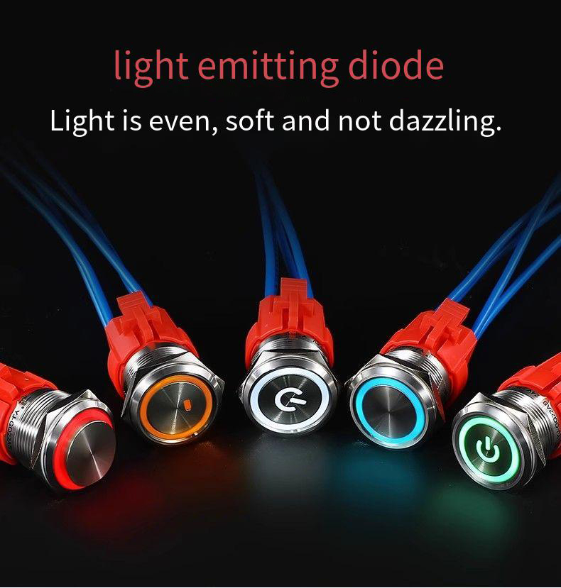
- Illuminated switches that include LEDs
Would you like tips on identifying your switch type before we dive deeper? Contact us now for expert advice and tailored solutions!
The Basics of Metal Push Button Switch Terminal Types
Each metal push button switch usually has multiple terminals, and understanding their roles makes wiring easy. Here’s the most common setup:
| Terminal Name | Marking | Common Function |
|---|---|---|
| COM (Common) | COM | The main terminal where current flows from |
| NO (Normally Open) | NO | Circuit connects when button is pressed |
| NC (Normally Closed) | NC | Circuit connects until button is pressed |
Other terminals might include pins for:
- LED indicators
- Multiple independent contacts (in multi-pole switches)
Note: Terminal markings can vary by manufacturer, so consulting datasheets is always recommended.
If you want, I can help you find your switch’s datasheet based on its model number!
Identifying Terminal Functions by Color and Position
Besides markings, terminal colors and their locations are practical hints:
| Terminal Color | Likely Function |
|---|---|
| Red / Pink | Commonly used for NC (Normally Closed) |
| Blue / Green | Commonly used for NO (Normally Open) |
| Black or Uncolored | Often the COM terminal |
Terminal Position Tips:
- In 2-pin switches, terminals usually represent NO and COM.
- For 4- or 5-pin switches, terminals often come in pairs for NO and NC circuits.
This color/position guide won’t replace a test but helps as a first step.
Ready to test your terminals next? Let’s talk about tools.
Metal Push Button Switch How to Test Terminal Functions Using a Multimeter
A multimeter is your go-to tool for confirming terminal functions quickly and safely.
Step-by-Step Guide:
- Set multimeter to continuity or resistance mode.
- Connect probes to pairs of terminals.
- Press the button and observe readings:
- Continuity / low resistance when pressed: between COM and NO terminals.
- Continuity when not pressed: between COM and NC terminals.
| Terminal Pair | Button Pressed | Button Released |
|---|---|---|
| COM – NO | Continuity | No continuity |
| COM – NC | No continuity | Continuity |
By following this you ensure wired circuits behave as expected, avoiding costly errors.
Feeling confident? If you prefer, we can walk through a real example or troubleshooting tips.
Need reliable, durable metal push button switches?
Contact us now for expert advice and tailored solutions!
Electrical Specifications and Environmental Considerations
Choosing the right metal push button switch means checking its ratings and build:
| Specification | Importance |
|---|---|
| Rated Voltage (V) | Prevents electrical overload |
| Rated Current (A) | Must meet or exceed your circuit’s demand |
| IP Protection | Ensures resistance to dust and water (IP65, IP67 common in metal switches) |
For industrial applications, pick switches with robust IP ratings to withstand harsh environments.
If you’d like, I can help match switches to your environment and load.
Common Wiring Mistakes and How to Avoid Them
Even experienced technicians occasionally struggle with switch wiring. Here are some pitfalls and solutions:
- Mistake: Confusing NO and NC terminals
- Fix: Verify with multimeter before wiring
- Mistake: Ignoring power rating, risking switch damage
- Fix: Always check voltage and current specs
- Mistake: Poor solder joints or loose connections
- Fix: Use proper soldering technique or secure fasteners
Table: Common Errors vs. Prevention
| Error | Cause | Prevention |
|---|---|---|
| Wrong terminal wiring | Misread markings or guesswork | Cross-check datasheet and test pins |
| Overload | Exceeding electrical limits | Match switch ratings properly |
| Insecure connections | Neglected wiring quality | Use appropriate tools and inspect |
Taking these steps saves time and increases product reliability.
Want a wiring checklist? I can draft one for your team.
Real-World Wiring Examples and Applications
Example 1: Simple 2-Pin Momentary Switch
| Step | Action |
|---|---|
| 1 | Connect power supply positive to one terminal |
| 2 | Connect other terminal to load |
| 3 | Connect load back to power supply negative |
Pressing the button completes the circuit, turning the load on momentarily.
Example 2: 4-Pin Switch with LED Indicator
| Terminal | Connection |
|---|---|
| COM | Power source positive |
| NO | Load input |
| LED + | Power positive for LED |
| LED – | Power negative for LED |
The LED illuminates when the switch is pressed, signaling activation.
Correctly identifying your metal push button switch terminals is no mystery once you know what to look for:
- Understand common terminal types: COM, NO, NC
- Use terminal markings, colors, and position clues
- Confirm with a multimeter test for certainty
- Follow electrical ratings and wiring best practices to ensure safe and reliable operation
We hope this guide has made wiring your metal push button switch YJ-GQ25B easier and more approachable. If you need high-quality Metal Push Button Switches or personalized wiring advice, don’t hesitate to contact our factory team for expert support and competitive pricing.
FAQ
Most metal push button switches have terminals labeled as COM (common), NO (normally open), and NC (normally closed). Use a multimeter to test continuity: when pressed, continuity appears between COM and NO; when released, between COM and NC.
Terminal colors often indicate function: blue or green usually means NO; red or pink typically means NC; black or uncolored terminals are commonly COM. However, always verify with a multimeter.
LED terminals are usually separate from the switch contacts. Connect LED positive (+) and negative (-) terminals to suitable power supply lines according to the datasheet. The switch contacts (COM, NO, NC) are wired separately to control your circuit.
No, most metal push button switches are designed for low current control circuits, usually up to 5A. For high current loads, use the switch to control a relay or contactor.
Double-check the LED wiring polarity and power supply voltage. The LED has polarity and requires the correct voltage. Also check if the LED is built-in or separate from the switch contacts.
Avoid mixing NO and NC terminals, using a switch beyond its current rating, and loose or cold solder joints. Always test terminals before wiring, use proper tools, and follow datasheets.