If you work with industrial control panels, chances are you deal with an alternating current relay switch almost every day. Yet many purchasing managers, system integrators, and even engineers still run into the same problems: Which relay should I choose? How do I wire it correctly? And how do I avoid failures once it’s installed?
This article is written for B2B buyers, OEMs, panel builders, and engineers who want more than textbook definitions. We’ll focus on how to wire AC relays, how to select the right model, and which configurations (SPDT, 4 pin, 3 way) make sense in real control panel applications.
Along the way, we’ll reference AC relay wiring diagrams, explain common terminal layouts, and give you practical selection advice you can apply directly to your next project—or purchasing decision.
Let’s start from the real-world perspective: you have a control panel, an AC load, and a relay in your hand—now what?
What Is an Alternating Current Relay Switch?
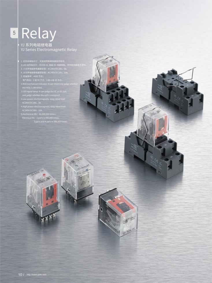
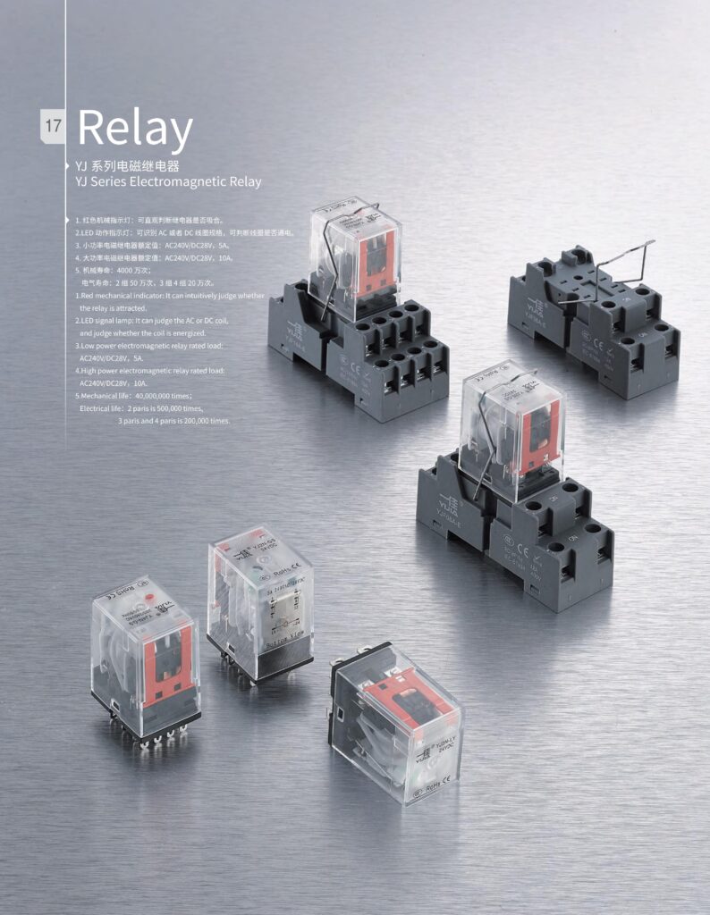
An alternating current relay switch is an electromechanical device that uses an AC control signal to open or close electrical contacts. In a control panel, it acts as a safe and reliable interface between low-power control circuits and high-power AC loads.
Unlike DC relays, AC relays are designed to handle:
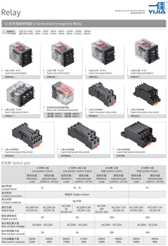
- AC coil voltages (110V, 120V, 220V, 230V, 240V)
- Inductive loads such as motors, solenoid valves, and transformers
- Frequent switching in industrial environments
From a buyer’s perspective, the relay is not just a component—it’s a risk control device. The wrong choice can cause contact welding, overheating, or nuisance failures.
Typical Control Panel Applications
| Application | Why an AC Relay Is Used |
|---|---|
| Motor starters | Isolate control circuit from motor current |
| HVAC control panels | Switch compressors, fans, heaters |
| Power distribution panels | Enable remote or automated switching |
| Industrial machinery | Interface PLC outputs with AC loads |

Understanding an AC Relay Wiring Diagram
Before choosing a relay, you need to understand how it’s wired. An AC relay wiring diagram shows two main sections:
- Coil side (control circuit)
- Contact side (load circuit)
They are electrically isolated, which is the key safety advantage.
Basic AC Relay Wiring Structure
| Section | Function | Typical Terminals |
|---|---|---|
| Coil | Energizes the relay | A1 / A2 |
| Common (COM) | Moving contact | COM |
| Normally Open (NO) | Closed when coil is energized | NO |
| Normally Closed (NC) | Open when coil is energized | NC |
When AC voltage is applied to the coil terminals, a magnetic field pulls the internal armature, changing the state of the contacts.
Why Wiring Diagrams Matter
Misreading a wiring diagram is one of the most common causes of relay failure. For example:
- Connecting AC load to coil terminals
- Confusing NO and NC contacts
- Using incorrect wire gauge for load current
A correct wiring diagram reduces downtime, warranty claims, and safety risks—all critical concerns for B2B buyers.
SPDT AC Relay Wiring Diagram Explained
One of the most searched configurations is the SPDT (Single Pole Double Throw) AC relay. It’s popular because it offers flexibility without added complexity.
What Does SPDT Mean in Practice?
An SPDT relay has:
- One common terminal (COM)
- One normally open (NO) contact
- One normally closed (NC) contact
The load can be switched between two circuits depending on the coil state.
SPDT Wiring Logic
| Coil State | COM Connected To | Typical Use Case |
|---|---|---|
| Coil OFF | NC | Default-safe condition |
| Coil ON | NO | Active operation |
This is especially useful in control panels where fail-safe behavior matters, such as emergency stop circuits or alarm systems.
When to Choose SPDT
Choose an SPDT alternating current relay switch if:
- You need status change logic
- You want a default ON or OFF state
- You’re designing a 3 way control logic (more on that later)
4 Pin AC Relay Wiring in Control Panels
A 4 pin AC relay is often the first choice for compact control panels. It’s simple, reliable, and cost-effective.
Typical 4 Pin Layout
| Pin Count | Function |
|---|---|
| 2 pins | AC coil |
| 2 pins | Switching contact (usually NO) |
This type is commonly used where only ON/OFF control is required.
How to Wire a 4 Pin AC Relay
The wiring process usually follows this flow:
- Connect the AC control voltage to the coil pins
- Route the load line through the contact pins
- Verify current rating matches the load
Because there’s no NC contact, wiring errors are less common—one reason purchasing teams favor 4 pin relays for standardized panels.
Limitations to Consider
| Advantage | Limitation |
|---|---|
| Compact size | No fail-safe NC option |
| Lower cost | Less flexible control logic |
| Easy wiring | Limited troubleshooting options |
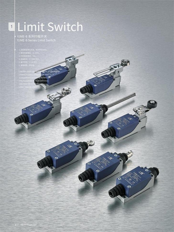
If you’re unsure whether the AC Relay Switch is right for your machine, simply share a sketch, stroke length, and environmental data, YIJIA supplier can recommend a suitable model.
3 Way AC Relay Wiring: How It Works
The term 3 way wiring is often misunderstood in industrial contexts. In relay applications, it usually refers to switching one load between two sources or states using an SPDT relay.
Typical 3 Way Wiring Scenario
Imagine:
- One motor
- Two possible control signals
- One alternating current relay switch
By wiring the load through COM and choosing NO/NC correctly, you can control which signal path is active.
Practical Example in Control Panels
| State | Result |
|---|---|
| Relay de-energized | Load powered via NC path |
| Relay energized | Load powered via NO path |
This is common in:
- Manual/automatic mode switching
- Redundant power source selection
- Alarm and indicator light logic
How to Choose the Right Alternating Current Relay Switch
This is where many buyers struggle. The datasheet looks fine—but is it right for your application?
Key Selection Parameters
| Parameter | What to Check |
|---|---|
| Coil voltage | 110V, 220V, 230V AC |
| Contact rating | Resistive vs inductive load |
| Contact form | SPDT, DPDT, NO only |
| Pin configuration | 4 pin, 5 pin, 8 pin |
| Mounting type | DIN rail, PCB, panel mount |
Load Type Matters More Than You Think
A motor load behaves very differently from a resistive heater. Always derate contacts for:
- Motors
- Solenoids
- Transformers
If you’re unsure, choosing a higher contact rating is safer and often reduces long-term maintenance costs.
Control Panel Integration Considerations
In real control panels, relays don’t work alone. They interact with:
- PLC outputs
- Push buttons
- Indicator lights
- Circuit breakers
Common Panel Design Tips
| Tip | Benefit |
|---|---|
| Label relay terminals clearly | Faster maintenance |
| Leave wiring slack | Easier replacement |
| Separate control and power wiring | Reduced interference |
For procurement teams, standardized relay models across panels simplify inventory and sourcing.
Common Wiring Mistakes to Avoid
Even experienced installers make these mistakes:
- Using a DC relay in an AC circuit
- Ignoring inrush current
- Misreading SPDT contact orientation
- Underrating contact current
Each of these can shorten relay life significantly.
Why Relay Quality Matters for B2B Buyers
For engineers, a relay is a technical decision. For buyers, it’s a risk and cost decision.
Low-quality relays may:
- Fail prematurely
- Cause system downtime
- Increase after-sales service costs
Choosing a reliable AC relay supplier with consistent specifications can significantly reduce long-term operating risk. If you’re sourcing relays for control panels, it’s often worth discussing your application directly with the manufacturer or sending a detailed inquiry before placing bulk orders.
An alternating current relay switch is a small component with a big impact. Understanding the AC relay wiring diagram, knowing when to use SPDT, 4 pin, or 3 way configurations, and selecting the right specifications are all critical to building reliable control panels.
Instead of asking “What is a relay?”, the better question is:
“How do I wire it correctly, and which one actually fits my application?”
When you get those answers right, you reduce failures, save costs, and build systems that last. And that’s exactly what engineers, buyers, and project managers all want—whether they say it out loud or not.
FAQ
No. AC coils and DC coils are designed differently. Using the wrong type can cause overheating or failure.
An SPDT wiring diagram is the most common in industrial control panels due to its flexibility.
For simple ON/OFF control, yes. For fail-safe logic, consider SPDT or DPDT relays.
Check the load type and current. For inductive loads, always add a safety margin.
Yes. An SPDT alternating current relay switch can handle basic 3 way wiring logic.