When you are specifying an ac relay switch for a new project or a mass production build, one of the first questions is: do I need an AC coil relay or a DC coil relay, and how do I wire it correctly? In this guide we will walk through how to identify AC vs DC coils, how to choose the right ac relay switch for B2B / OEM applications, and how to wire common SPDT, 4‑pin and 3‑way relay configurations step by step.
If at any point you prefer a ready‑to‑use solution instead of calculating everything yourself, you can always send us your load data and wiring diagram and we will recommend a specific relay model for you.
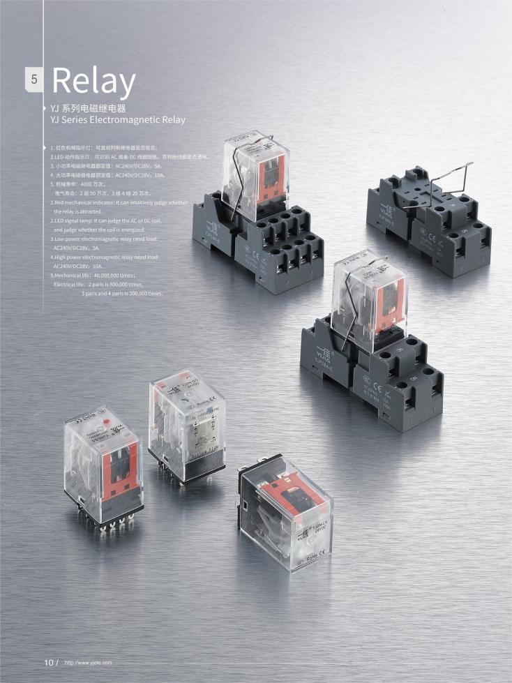
AC coil vs DC coil relay basics
AC and DC relay coils look similar from the outside, but they are designed very differently and are not interchangeable in normal operation. An ac relay switch with the wrong coil type can overheat, fail to pull in, or weld contacts, which is unacceptable in OEM equipment and control panels.
At a basic level:
- An AC coil relay is designed to be powered by mains or low‑voltage AC (for example 24 VAC, 110 VAC, 230 VAC).
- A DC coil relay is designed for DC supply (for example 5 VDC logic, 12 VDC, 24 VDC in automotive and industrial control).
- The contact side (the “switch” side) of both can be used to switch AC or DC loads within the rated contact voltage and current, which is independent from the coil voltage.
How the coils differ electrically
AC coils rely heavily on inductive reactance as part of their design, while DC coils rely mostly on resistance.
- For AC, the coil current is determined by R2+XL2R2+XL2, where XLXL is the inductive reactance at the line frequency; this limits current and stabilizes the coil.
- For DC, there is no inductive reactance in steady state, so coil current is mainly set by the wire resistance.
Because of that:
- If you connect a DC coil relay to AC at its DC rating, it may not pull in properly because the inductive reactance at 50/60 Hz increases total impedance.
- If you connect an AC coil relay to DC at its AC rating, the inductive reactance disappears, current is limited only by resistance, and the coil can overheat or burn out.

How to visually identify AC vs DC relay coils
Engineers often need to make a quick decision in the field with minimal documentation. Here are practical indicators.
- Label on housing:
- Coil wire and turns:
- Core structure:
- Thermal design:
Quick comparison table: AC vs DC coil relays
If you are not sure, never guess: always cross‑check the marking with the datasheet or send us a photo of your relay for confirmation.
How to choose the right AC relay switch (coil and contacts)
From a B2B / purchasing perspective, choosing an ac relay switch is less about one specification and more about matching a full set of coil and contact parameters to your real load.
You can walk through a simple nine‑step logic:
- Define the function (on/off, change‑over, motor direction, 3‑way switching).
- Confirm the coil voltage and type (AC vs DC, logic level vs mains).
- Pick the contact configuration (SPST, SPDT, DPDT, 3‑way, etc.).
- Match the contact current and voltage rating to your load.
- Check coil power and drive capability of your control side.
- Validate electrical life at your load (duty cycle, inrush, DC vs AC).
- Choose mounting style (PCB, plug‑in, panel, DIN).
- Verify creepage/clearance and safety approvals (UL, VDE, etc.) where needed.
- Standardize part numbers to simplify future procurement.
Coil selection for engineering teams
Engineers usually start with the coil, because it must match whatever control signal is available (PLC output, microcontroller, relay driver, mechanical switch, or power supply).
For coil selection:
- Match coil voltage exactly (for example 24 VAC coil on 24 VAC, 12 VDC on 12 VDC); over‑ or under‑voltage severely reduces life.
- Check coil power (for example 0.36 W, 0.6 W, 1.2 W) and ensure the controlling device can supply enough current.
- Compare pick‑up and drop‑out voltages with your worst‑case system supply variations.
Contact selection for buyers and project managers
On the contact side, B2B customers mainly care about current, voltage and lifetime.
- Use the rated current as a guideline, not a guarantee: a 16 A relay at 250 VAC resistive may not tolerate 16 A motor inrush.
- Check if the vendor provides specific ratings for inductive loads, motors, LEDs, or capacitive loads.
- Look at electrical life spec (for example 100k operations at rated load) to estimate cycle life in your product.
Quick selection table for purchasing
If you share your load type, nominal voltage, and required lifetime, we can help you shortlist concrete relay series and coil versions for your project.
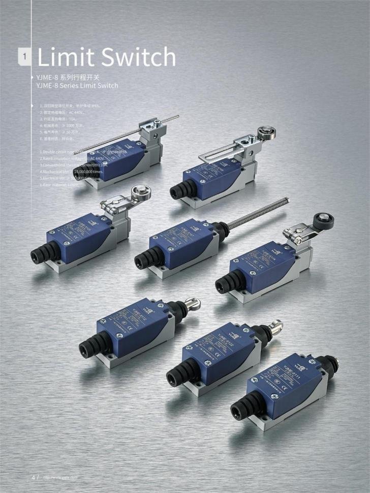
If you’re unsure whether the AC Relay Switch is right for your machine, simply share a sketch, stroke length, and environmental data, YIJIA supplier can recommend a suitable model.
Wiring an AC relay switch: SPDT, 4‑pin, 5‑pin and 3‑way
Many engineers search directly for terms like “ac relay switch wiring diagram” or “SPDT 4 pin relay wiring” when they just want to know “which wire goes where”. Below are practical wiring guides you can adapt to your own schematics.
Understanding common relay pins (automotive style)
Most plug‑in relays use a standardized numbering scheme.
- 85, 86: Coil pins (AC or DC depending on relay type).
- 30: Common contact (COM), the moving arm of the switch.
- 87: Normally‑open (NO) contact.
- 87a: Normally‑closed (NC) contact, present on 5‑pin SPDT relays.
On some PCB relays, the same functions appear without numbers but with symbols on the case or datasheet.
4‑pin relay (SPST) wiring: how to connect
A 4‑pin relay typically has one coil pair and one SPST contact (either NO or NC).
- Step 1: Identify coil pins (usually 85 and 86).
- Step 2: Connect one coil pin to your control signal (for example thermostat output, PLC output, or manual switch).
- Step 3: Connect the other coil pin to the return (neutral for AC coil, or ground for DC coil).
- Step 4: Connect COM (pin 30) to the supply line of the load circuit (for example 230 VAC line).
- Step 5: Connect NO (pin 87) to one side of your load; the other side of the load goes to neutral (AC) or ground (DC).
When the coil is energized, the ac relay switch closes between pins 30 and 87 and powers the load.
5‑pin relay (SPDT) wiring: classic SPDT / 3‑way logic
A 5‑pin relay gives you both NO and NC contacts, enabling SPDT or 3‑way style switching between two circuits.
- Step 1: Connect pin 85 to ground or neutral depending on coil type.
- Step 2: Connect pin 86 to your control signal (for example 24 VDC from a controller or 24 VAC from a thermostat).
- Step 3: Connect pin 30 to the common supply that you want to route (for example a motor feed or lamp supply).
- Step 4: Connect pin 87 (NO) to load 1, and 87a (NC) to load 2 if you need to switch between two loads.
In an SPDT configuration, when the coil is de‑energized, COM is connected to NC (87a); when energized, COM switches to NO (87). This is functionally similar to a 3‑way switch in power circuits, commonly used for two‑position control.
Practical 3‑way use case with an ac relay switch
For example, suppose you need to switch a single AC motor between “forward” and “reverse.” You can use an SPDT relay with appropriate motor contact wiring so that one position energizes the forward winding and the other energizes the reverse winding, making sure you follow motor and relay datasheet constraints. The COM contact carries your AC supply, while NO and NC route power to different winding configurations.
For safety: add proper interlocks, fuses, and respect the motor’s inrush current; otherwise, contact life may be much shorter than the rated electrical life.
Wiring summary table (SPDT / 4‑pin / 5‑pin)
If you send us your current schematic in PDF or photo, we can annotate the exact pin‑to‑pin wiring for your relay choice.
Common mistakes and how to avoid them
Even experienced engineers occasionally misinterpret relay specifications, especially when combining AC and DC coils in the same panel. A few typical pitfalls appear again and again in field complaints and warranty returns.
Confusing coil ratings with contact ratings
One classic error is to assume that because a relay is labeled “24 VDC” it can only be used in 24 VDC circuits. In reality, that label is usually the coil rating; the contacts may be rated for 250 VAC at some amperage. Always distinguish:
- Coil rating: what you need on the control side to energize the relay.
- Contact rating: what you can safely switch on the load side.
Datasheets typically list these in separate tables; mixing them up can lead to underspecified relays in AC mains applications.
Using DC coils on AC or vice versa
As discussed above, DC coils on AC may fail to pull in, while AC coils on DC can overheat. This is more than a theoretical issue; it can cause sporadic failures in the field that are hard to reproduce in the lab.
A simple rule:
- If the relay case says “24 VDC,” only drive the coil with DC; if it says “24 VAC,” never connect it to DC unless the datasheet explicitly allows it.
Underestimating inrush current
Motor loads, transformer primaries and LED power supplies can draw several times their nominal current at switch‑on. If you size the ac relay switch purely by steady‑state current, contacts may weld or burn after only a few hundred cycles.
Look for:
- Specific “motor load” or “inrush” ratings in the datasheet.
- Application notes on derating for inductive or capacitive loads.
Quick troubleshooting table
If you want to reduce such issues across a whole product line, standardizing on a proven ac relay switch family and testing with your worst‑case load is one of the quickest wins.
FAQ
Check the printing on the case: it should say something like “12 VDC” or “24 VAC”; you can also look for a shading ring and E‑shaped core for AC, while DC coils often have more turns of thinner wire.
Generally no; DC coils rely on resistance only, so on AC they may not generate enough magnetic flux at the zero crossings and can fail to pull in or overheat.
An SPDT relay has one common contact and both NO and NC outputs, letting you switch between two circuits or implement a 3‑way style change‑over; you should choose it when you need “one input, two selectable outputs” in your design.
Connect the two coil pins to your control voltage and its return, then connect COM to the supply line and NO to the load, with the other side of the load returning to neutral or ground.
Connect the coil pins to your control signal and return, connect COM to the source, connect NO to load 1 and NC to load 2 so that energizing the coil toggles which load is active.
Look for an ac relay switch with an appropriate AC coil for your control voltage and contact ratings at least 250 VAC, 12–16 A resistive, and confirm electrical life at your target cycle count in the datasheet.
Choose a low‑power coil variant (for example 0.25–0.36 W) whose pick‑up current is comfortably below your PLC’s maximum output specification.