A limit switch sensor is a device used to detect the position or movement limit of an object. When an object moves to a predetermined position or exceeds a specified range, the limit switch sensor sends a signal to control the start, stop, or change direction of the equipment. They are commonly used in industrial automation, mechanical equipment, and safety systems to ensure that the equipment works along a predetermined path or range to prevent accidents and equipment damage.
Limit switch sensors have the characteristics of simple structure, easy installation, low cost, and high reliability. They are usually composed of mechanical contacts or electronic components and can operate stably in harsh working environments. Common limit switch sensors include mechanical, photoelectric, inductive, and capacitive types, and are widely used in automated production lines, lifting equipment, conveying systems, and robots.
Through the use of limit switch sensors, industrial equipment and systems can achieve precise positioning and control, improve production efficiency and safety. At the same time, they can also play an important role in automated control systems in homes and commercial places.
Limit switch sensor components
Limit switch sensors consist of several key components, each with its own specific function to ensure that the sensor can accurately detect position and motion limits. The following are the main components of limit switch sensors:
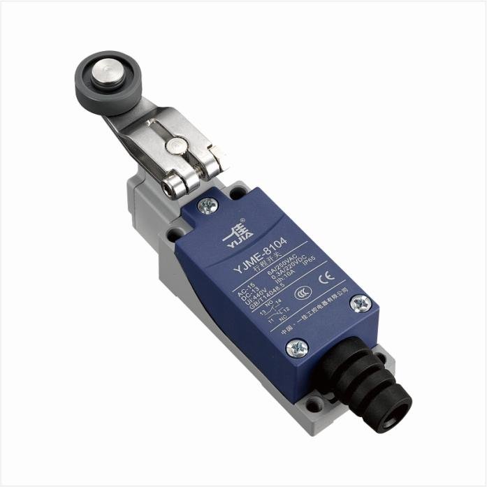
Actuator: The actuator is the sensing part of the limit switch sensor and is in direct contact with the moving object. Depending on the design, the actuator can be a rotating arm, a slide bar, a roller, or a button. When the object reaches the predetermined position, the actuator is triggered, thereby triggering the switch inside.
Switch body: The switch body contains the internal electrical switching elements. It is the core part of the limit switch sensor and is responsible for converting the mechanical action of the actuator into an electrical signal. The switch body is usually made of sturdy materials to withstand frequent operations and harsh working environments.
Contact system: The contact system is a key part inside the switch body. When the actuator is triggered, it causes the contacts to close or open, thereby completing the on-off of the circuit. The contact system can be in multiple forms such as single-pole double-throw (SPDT), single-pole single-throw (SPST), or double-pole double-throw (DPDT) to meet different control needs.
Housing: The housing is the protective part of the limit switch sensor, enclosing and protecting the internal components from dust, moisture and other environmental factors. The housing is usually made of metal or high-strength plastic, with good sealing and durability.
Terminals: Terminals are used to connect the limit switch sensor to the external circuit. They are usually located on the outside of the switch body and fix the wires with screws or spring clips to ensure the stability and security of the electrical connection.
Reset device: Some limit switch sensors are equipped with a reset device that automatically resets after being triggered. The reset device can be a spring or other mechanical mechanism to ensure that the sensor returns to its initial state after each operation and is ready for the next detection.
Limit switch sensor working principle
The working principle of the limit switch sensor is mainly based on the process of mechanical action and electrical signal conversion. When the object moves to the predetermined position, the limit switch sensor sends a signal through the internal mechanical contacts or electronic components to achieve the control purpose. The following is the detailed working principle of the limit switch sensor:
Mechanical triggering
When the monitored object (such as a robotic arm or conveyor belt) moves to the predetermined position, it contacts the actuator (such as a button, roller or lever) of the limit switch sensor. This action pushes the actuator to move, thereby triggering the internal switch.
Contact action
The movement of the actuator acts on the internal contact system. The contact system is made of conductive materials, and when the contacts are closed or opened, the state of the circuit is changed. Generally, the contact system has two states:
Normally open (NO): In the untriggered state, the contacts are open, and when the actuator is triggered, the contacts are closed to complete the circuit.
Normally closed (NC): In the untriggered state, the contacts are closed, and when the actuator is triggered, the contacts are open to disconnect the circuit.
Electrical signal output
After the contact is actuated, the state of the circuit changes, thereby generating an electrical signal. These signals can be switch signals (on/off signals) used to control relays, PLCs (programmable logic controllers) or other control systems.
Reset process
After being triggered, some limit switch sensors are equipped with a reset device, such as a spring or other mechanical mechanism. When the object leaves the actuator of the limit switch sensor, the reset device will restore the actuator to its initial position, and the contact system will also be restored to its initial state, ready for the next detection.
Specific workflow
Movement of the object to be detected: When a mechanical device or a moving object approaches the limit switch sensor, it will first contact the actuator of the sensor.
Actuator is triggered: The movement of the object pushes the actuator (such as a button or lever) to move.
Contact system action: The displacement of the actuator acts on the internal contact system, causing the contacts to close or open, changing the circuit state.
Signal output: The change in the state of the contact system generates an electrical signal, which is transmitted to the control system for corresponding processing (such as stopping the machine, alarming or other operations).
Actuator reset: After the object leaves, the reset device restores the actuator to its initial position, and the contact system also restores its initial state, ready for the next operation.
Limit switch sensor types
There are many types of limit switch sensors, each with its own characteristics and advantages depending on its working principle and application scenario. The following are common types of limit switch sensors:
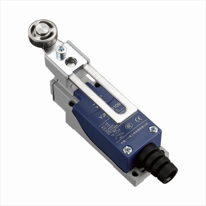
Mechanical limit switch
Features: Use mechanical contacts for position detection, common actuators include buttons, rollers and levers.
Advantages: Simple structure, low cost, long service life.
Application: Suitable for position detection in mechanical equipment, production lines and automation systems.
Photoelectric limit switch
Features: Use light beams for detection, and the sensor sends a signal when the object blocks or reflects the light beam.
Advantages: No mechanical wear, fast response speed, adjustable detection distance.
Application: Widely used in automated production lines, packaging machinery and safety protection systems.
Inductive limit switch
Features: Works by detecting the inductive changes of metal objects, without contacting the object being measured.
Advantages: Wear-resistant, suitable for harsh environments, high detection accuracy.
Application: Suitable for metal processing, mechanical equipment and automation control systems.
Capacitive limit switch
Features: Works by detecting the capacitance changes of objects, and can detect metal and non-metal objects.
Advantages: high sensitivity, wide detection range, no need to directly contact the object.
Application: suitable for material handling, liquid level detection and packaging industries.
Hall effect limit switch
Features: use magnetic field changes for detection, and output signals when magnetic objects approach or move away from the sensor.
Advantages: no mechanical wear, fast response speed, high reliability.
Application: suitable for automation equipment, door control system and position detection.
Magnetic limit switch
Features: works by detecting the position change of magnetic objects, usually using magnets as trigger elements.
Advantages: no power supply required, suitable for high temperature and harsh environment.
Application: widely used in industrial automation, door and window control and security systems.
Comparison of various types of limit switches
Mechanical vs photoelectric: mechanical structure is simple but has mechanical wear, photoelectric is contactless but affected by ambient light.
Inductive vs capacitive: inductive focuses on metal object detection, while capacitive can detect metal and non-metal objects.
Hall effect vs magnetic: Hall effect requires power but has high accuracy, while magnetic does not require power but is affected by magnetic field strength.
There are various types of limit switch sensors, each with its own advantages and disadvantages. Choosing the right type depends on the specific application scenario and detection requirements. By properly selecting and applying limit switch sensors, the automation level and operational reliability of the equipment can be effectively improved.
Application scenarios
Limit switch sensors are widely used in various industrial and commercial applications to ensure precise control and safe operation of equipment. Here are some common application scenarios:
Automated production line
Function: In the production line, limit switch sensors are used to detect the position of workpieces, control the movement of robotic arms, monitor the operation of conveyor belts, etc.
Application example: For example, when a workpiece moves to a specified position, the limit switch sensor will send a signal to trigger the robotic arm to perform welding or assembly operations.
Lifting equipment
Function: In equipment such as elevators, cranes and lifting platforms, limit switch sensors are used to detect the extreme positions of the range of motion to prevent equipment from overtravel or collision.
Application example: When the elevator reaches each floor, the limit switch sensor will detect and trigger the elevator to stop to ensure safe parking.
Conveyor system
Function: In the conveyor belt system, the limit switch sensor is used to detect the arrival or departure position of the material and control the start and stop of the conveyor belt.
Application example: When the material passes through the limit switch sensor, the sensor will send a signal to stop the conveyor belt to prevent material accumulation or overflow.
Mechanical equipment
Function: In various types of mechanical equipment, limit switch sensors are used to detect the position of mechanical parts to ensure that the equipment runs according to the predetermined path.
Application example: In CNC machine tools, limit switch sensors detect the position of the tool to prevent the tool from exceeding the processing range and avoid damaging the workpiece or equipment.
Robots
Function: In robot systems, limit switch sensors are used for position detection and motion control to ensure that the robot performs tasks according to the programmed path.
Application example: When the robot arm moves to a specific position, the limit switch sensor will send a signal to trigger the next operation, such as grabbing or placing an object.
Gate control system
Function: In systems such as automatic doors, garage doors, and security doors, limit switch sensors are used to detect the opening and closing status of the door and control the automatic opening and closing of the door.
Application example: When the garage door is fully opened or closed, the limit switch sensor will send a signal to stop the motor from running to prevent excessive opening and closing from damaging the door body.
Industrial safety system
Function: In industrial safety systems, limit switch sensors are used to detect the position of equipment in dangerous areas to prevent people or equipment from entering dangerous areas.
Application example: Set limit switch sensors in the dangerous area of production equipment. When the equipment moves to the dangerous area, the sensor will sound an alarm or stop the equipment to ensure personnel safety.
Household appliances
Function: In household appliances such as washing machines and microwave ovens, limit switch sensors are used to detect the opening and closing status of the door and control the working status of the appliance.
Application example: When the washing machine door is closed, the limit switch sensor triggers the start of the washing program; when the door is opened, the washing program stops to ensure safety.
How to choose the right limit switch sensor
There are several factors to consider when selecting a limit switch sensor to ensure its performance and reliability in a specific application. Here are the main factors to consider when selecting a limit switch sensor:
Application Environment
Temperature: Ensure that the sensor can work properly within the temperature range of the operating environment.
Humidity: Choose a limit switch with waterproof and moisture-proof properties to adapt to humid or watery environments.
Dust and pollution: For dusty or polluted environments, choose sensors with sealed designs, such as products with high IP ratings.
Workload
Current and voltage: Select the corresponding limit switch based on the electrical parameters of the application (such as current and voltage) to ensure that its contacts can withstand the actual workload.
Mechanical life: Consider the mechanical life of the sensor and choose a product that can meet the application frequency and service life requirements.
Detection distance and accuracy
Detection distance: Select the appropriate detection distance according to actual needs to ensure that the sensor can accurately detect the position within the required range.
Accuracy: Different applications have different accuracy requirements. High-precision applications require high-precision limit switches.
Contact form
Single-pole single-throw (SPST): Suitable for simple on/off control.
Single-pole double-throw (SPDT): Suitable for applications that require switching between two circuits.
Double-pole double-throw (DPDT): Suitable for complex control systems.
Actuator
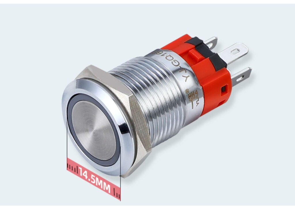
Button type: Suitable for occasions that require precise positioning.
Roller type: Suitable for contact detection of moving objects to reduce friction.
Lever type: Suitable for large-scale motion detection with high sensitivity.
Installation method
Fixed method: Select a limit switch suitable for the installation space and method to ensure stable and convenient installation.
Wiring method: Select a suitable wiring method according to actual needs, such as screw wiring, welding wiring or quick connector.
Reset method
Automatic reset: Suitable for applications with continuous detection, the sensor can automatically restore to the initial state.
Manual reset: Suitable for applications that require manual reset to ensure the operability of the control.
Durability and reliability
Material: Select a limit switch made of durable materials that can work for a long time in harsh environments.
Brand and quality: Choose a reputable brand and certified products to ensure their quality and reliability.
Selection steps
Identify application requirements: Determine specific application scenarios and requirements, such as environmental conditions, workload, detection distance and accuracy.
Filter products: Filter suitable limit switch sensor types and models according to requirements.
Evaluate performance: Check product specifications and performance parameters to ensure that they meet application requirements.
Test verification: Test in actual applications to verify its performance and reliability.
Final selection: Select the most suitable limit switch sensor based on test results and comprehensive considerations.
What is a relay switch board A relay switch board is an electronic device that contains multiple relay components used to control one or more electrical loads in an electrical circuit. This device activates a relay by receiving an external control signal, thereby opening or closing the path for current to flow to a specific […]
What is SPDT push button switch SPDT push button switch, the full name is Single Pole Double Throw (Single Pole Double Throw) push button switch, is a common electrical switch. Its structure allows it to connect an input circuit to either of two different output circuits, often used to control the flow of electrical current. […]
A limit switch is a mechanical switch whose main function is to detect or limit the movement of an object to a specific position. This kind of switch is usually designed to be mechanical, and its action is often caused by moving objects. Once an object triggers the switch, the switch changes its electrical state, […]
We use cookies to enhance your browsing experience, serve personalised ads or content, and analyse our traffic. By clicking "Accept All", you consent to our use of cookies.