Learn more about the working principles of various limit switches
How does a limit switch work?
A limit switch is a device used to detect the position of objects and control mechanical movement. It is widely used in industrial automation and mechanical equipment. Its main function is to control the equipment by detecting position changes in mechanical movement. The working principle of the limit switch can be summarized as follows: when the mechanical moving part reaches the predetermined position, the limit switch is triggered, thereby changing the state of the circuit and completing the corresponding control operation. The following is the detailed working principle of the limit switch:
Working principle
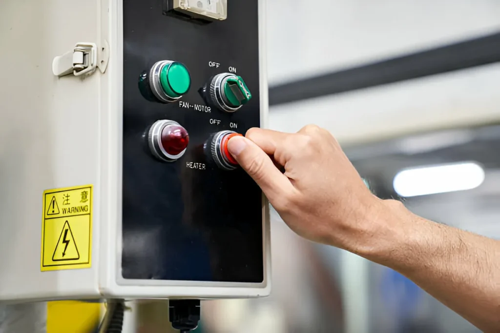
1. Physical triggering: Limit switches are usually installed at specific positions of mechanical equipment. When the moving parts move to a predetermined position, they will contact and trigger the operating mechanism of the limit switch. The operating mechanism can be a button, rod, roller or other form. Mechanical components.
2. Contact changes: After the operating mechanism is triggered, the contacts inside the limit switch will change, usually through mechanical connection. This causes the circuit to break. Limit switches usually have two contact states:
Normally open contact (NO, Normally Open): The contact is open in the initial state and closed after triggering.
Normally closed contact (NC, Normally Closed): The contact is closed in the initial state and opens after triggering.
3. Signal transmission: After the contact changes, the limit switch will send an electrical signal to the control system. After receiving the signal, the control system will perform corresponding operations according to the preset logic, such as starting or stopping the motor, triggering an alarm, or performing other control actions.
4. Reset mechanism: When the mechanical moving parts leave the triggering position of the limit switch, the limit switch will automatically reset and the contacts will return to the initial state, ready for the next operation.
Applications
Limit switches are widely used in various industrial equipment, such as:
Automated production line: used to detect whether the workpiece reaches the designated position and trigger the next process.
Lift: Ensure that the lifting platform stops when it reaches a specific floor to ensure safety.
Conveyor belt system: detects the position of objects on the conveyor belt and controls the start and stop of the conveyor belt.
Features and Benefits
Precise control: The limit switch can accurately detect the mechanical position and provide high-precision control.
High reliability: solid structure, long life, and able to work reliably in harsh environments.
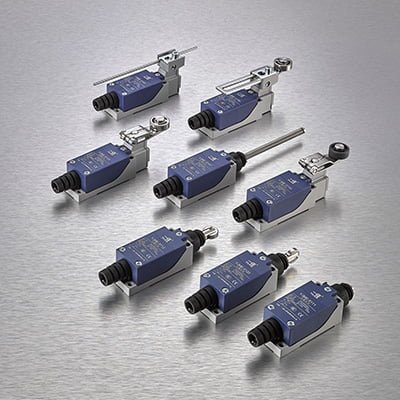
Diversity: According to different application requirements, limit switches have various types and specifications, such as mechanical, magnetic, photoelectric, etc., to meet the usage requirements of different scenarios.
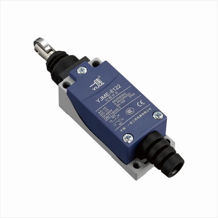
How mechanical limit switches work
Mechanical limit switches are the most common type of limit switches and are widely used in industrial automation and mechanical equipment. Its main principle is to trigger the internal switch through mechanical contact, thereby realizing the on and off of the circuit. The following is the detailed working principle of mechanical limit switch:
Structure and composition
Mechanical limit switches usually consist of the following main parts:
Operating head: This is the part in direct contact with external mechanical moving parts, which can be in the form of buttons, levers, rollers, etc.
Drive rod: The component that connects the operating head and the internal switch mechanism to transmit external mechanical force.
Switching mechanism: The internal portion of an electrical switch containing the contacts and spring assembly.
Shell: protects internal components and provides mechanical strength and protection.
Working principle
Trigger process:
When the moving parts of the mechanical equipment contact the operating head of the limit switch, the operating head is pushed or pressed.
This force is transmitted to the switching mechanism via the drive rod.
Contact action:
The drive rod pushes a spring in the switch mechanism, causing the state of the internal contacts to change.
In the case of a normally open contact (NO), the contact changes from open to closed.
In the case of a normally closed contact (NC), the contact changes from closed to open.
Circuit switching:
A change in the contact’s state switches the circuit on and off, thereby sending a signal to the control system.
The control system performs predetermined operations based on the received signals, such as stopping the motor, triggering an alarm, etc.
Reset process:
When the mechanical moving parts leave the limit switch, the spring device returns the operating head and drive rod to their original position.
The contacts then return to their initial state, ready for the next trigger.
Applications
Conveyor belt system: On the conveyor belt, mechanical limit switches are used to detect the position of the material and control the start and stop of the conveyor belt.
Automated production line: used to determine whether the workpiece has reached the designated station, thereby triggering the start of subsequent processes.
Lifts and lifting equipment: Ensure that the equipment stops automatically when it reaches the designated location to prevent it from exceeding the safety range.
Features and Benefits
High precision: Mechanical limit switches can provide precise position detection and are suitable for application scenarios that require high-precision control.
Strong reliability: The structure is simple and solid, and it can work stably for a long time in various harsh environments.
Easy to maintain: Mechanical components are easy to inspect and replace, resulting in lower maintenance costs.
How does a magnetic limit switch work?
Magnetic limit switch is a device that uses magnetic field changes to detect the position of objects and control circuit on and off. It is widely used in various industrial and automation equipment. The main principle is to detect the presence or change of the magnetic field through magnetic field sensing elements (such as Hall effect sensors or reed switches) to achieve switch operation. The following is the detailed working principle of the magnetic limit switch:
Structure and composition
Magnetic limit switches usually consist of the following main parts:
Magnetic sensor: used to sense changes in magnetic fields. Common ones include Hall effect sensors and reed switches.
Magnet: A permanent magnet or electromagnet that provides a magnetic field.
Switch mechanism: The part that receives the sensor signal and controls the circuit on and off.
Enclosure: Protects internal components and provides mechanical strength and protection.
Working principle
Magnetic field induction:
When a moving part of a mechanical device carries a magnet close to a magnetic limit switch, the magnetic field affects the magnetic sensor.
Specifically, Hall effect sensors produce a change in voltage in the presence of a magnetic field, while reed switches close or open in response to a magnetic field.
Signaling:
After the magnetic sensor detects changes in the magnetic field, it will generate a corresponding electrical signal.
This electrical signal is passed to the switching mechanism via wires.
Circuit switching:
After receiving the signal from the sensor, the switch mechanism controls the state changes of the internal contacts to turn the circuit on and off.
Common configurations include normally open contacts (NO) and normally closed contacts (NC), and different control logics are implemented according to design requirements.
Reset process:
When the magnet leaves the sensing range of the magnetic limit switch, the sensor returns to its initial state and the contacts return to their original state, ready for the next operation.
Applications
Door and window security system: used to detect the opening and closing status of doors and windows, and provide security protection and alarm functions.
Automated machinery and equipment: trigger control signals when moving parts reach designated positions to ensure precise positioning.
Liquid level detection: Through the combination of float ball and magnetic limit switch, the liquid level detection and control of the liquid container is realized.
Features and Benefits
Non-contact detection: Magnetic limit switches achieve non-contact detection through magnetic field induction, reducing mechanical wear and maintenance requirements.
High sensitivity: Able to accurately detect small magnetic field changes and achieve high-precision control.
Strong environmental resistance: suitable for various harsh environments, such as moisture, dust, etc., with high reliability.
Diversity: According to different application requirements, magnetic limit switches are available in various types and specifications to meet the usage requirements of different scenarios.
Working principle of photoelectric limit switch
Photoelectric limit switch is a device that uses photoelectric sensing technology to detect the position of objects and control circuit on and off. It is widely used in industrial automation and equipment control. Its main principle is to sense the presence of objects through the interruption or reflection of light beams, thereby achieving switching operations. The following is the detailed working principle of the photoelectric limit switch:
Structure and composition
Photoelectric limit switches usually consist of the following main parts:
Light emitting device: usually a light emitting diode (LED), used to emit light beams.
Receiving device: usually a photodiode or phototransistor, used to receive the light beam.
Signal processing circuit: Convert the received optical signal into an electrical signal and process it to control the on and off of the switch.
Shell: protects internal components and provides mechanical strength and protection.
Working principle
Beam transmitting and receiving:
Light-emitting devices (such as LEDs) emit a beam of light, usually infrared light, to avoid visible light interference.
The receiving device (such as a photodiode) is located opposite or at a certain angle to the light-emitting device and is responsible for receiving the light beam.
Beam interruption or reflection:
When there is no object blocking the beam, the beam will reach the receiver directly and the receiver will output a stable signal.
When an object enters the beam path, the beam is interrupted or reflected, and the receiver detects changes in the optical signal.
Signal processing:
The receiving device converts the received optical signal into an electrical signal and transmits it to the signal processing circuit.
The signal processing circuit analyzes the changes in the signal and controls the switching on and off according to the preset logic.
Circuit switching:
According to the signal processing results, the internal contact state of the photoelectric limit switch changes to realize the on and off of the circuit.
This is usually used to trigger the next action of the control system, such as stopping the machine, alarming, etc.
Applications
Automated production line: used to detect the position of the workpiece to ensure that the workpiece reaches the designated workstation accurately, thus triggering subsequent operations.
Access control system: detects the opening and closing status of the door and realizes automatic door opening or alarm function.
Material handling system: monitors the position of materials on the conveyor belt and controls the start and stop of the conveyor belt.
Features and Benefits
Non-contact detection: The photoelectric limit switch realizes non-contact detection through light beams to avoid mechanical wear and extend service life.
High precision: Photoelectric sensors can detect tiny objects and position changes to achieve high-precision control.
Fast response: The photoelectric limit switch responds quickly and is suitable for occasions that require rapid detection and control.
Wide scope of application: It is suitable for various complex environments, such as high temperature, high humidity, dust and other environments and can still work stably.
How hydraulic limit switches work
Hydraulic limit switch is a device that uses pressure changes in the hydraulic system to detect mechanical position and control circuit on and off. It is widely used in hydraulic equipment and systems. Its main principle is to trigger the switch through pressure changes in the hydraulic system to control the equipment. The following is the detailed working principle of the hydraulic limit switch:
Structure and composition
Hydraulic limit switches usually consist of the following main parts:
Pressure sensor: used to detect pressure changes in hydraulic systems.
Switching mechanism: converts the signal of the pressure sensor into an electrical signal and controls the circuit on and off.
Shell: protects internal components and provides mechanical strength and protection.
Working principle
Pressure detection:
Hydraulic limit switches are installed at specific locations in the hydraulic system. When the fluid pressure in the hydraulic system reaches a set value, the pressure sensor detects this change.
Signaling:
Pressure sensors convert detected pressure changes into electrical signals.
This electrical signal is passed to the switching mechanism via wires.
Contact action:
When the pressure reaches a predetermined setpoint, the contacts in the switching mechanism change, usually through a mechanical connection.
The contact change can be a normally open contact (NO) closing or a normally closed contact (NC) opening.
Circuit switching:
A change in the contact’s state switches the circuit on and off, thereby sending a signal to the control system.
The control system performs predetermined operations based on the received signals, such as starting or stopping the hydraulic pump, triggering alarms, etc.
Reset process:
When the pressure in the hydraulic system returns to normal levels, the pressure sensor returns to its initial state, and the contacts return to their original state, ready for the next operation.
Applications
Hydraulic press: In a hydraulic press, when the pressure reaches the set value, the hydraulic limit switch will be triggered to control the movement of the press to stop or start the next operation.
Hydraulic lifting platform: used to detect the height position of the lifting platform to ensure that the platform stops rising or falling when it reaches the set height to ensure safety.
Hydraulic system protection: Used to monitor the pressure in the hydraulic system. When the pressure exceeds the safe range, trigger an alarm or stop the hydraulic pump to prevent system damage.
Features and Benefits
High precision: Hydraulic limit switches can accurately detect pressure changes in the hydraulic system and achieve high-precision control.
Strong reliability: The structure is sturdy and can work stably for a long time in high pressure and harsh environments.
High sensitivity: The pressure sensor can quickly respond to pressure changes and is suitable for occasions that require rapid detection and control.
Diversity: According to different application requirements, hydraulic limit switches have various types and specifications to meet the use requirements of different scenarios.
How the temperature limit switch works
Temperature limit switch is a device that uses temperature changes to detect mechanical position and control circuit on and off. It is widely used in systems that require temperature monitoring and control. Its main principle is to sense temperature changes through a temperature sensor, and trigger the switch when the temperature reaches the set value, thereby achieving protection and control of the equipment. The following is the detailed working principle of the temperature limit switch:
Structure and composition
Temperature limit switches usually consist of the following main parts:
Temperature sensor: Common ones include bimetallic sheets, thermistors, thermocouples, etc., used to sense temperature changes.
Switch mechanism: converts the signal of the temperature sensor into mechanical action and controls the circuit on and off.
Enclosure: Protects internal components and provides mechanical strength and protection.
working principle
Temperature sensing:
Temperature sensors are installed at key locations of the equipment or system being monitored to sense temperature changes in real time.
When the temperature reaches a preset threshold, the temperature sensor undergoes changes in physical or electrical characteristics.
Trigger mechanism:
Bimetallic sheet: It is composed of two metal sheets with different expansion coefficients. When the temperature changes, the bimetallic sheet will bend, triggering the switch action.
Thermistor: The resistance value changes with temperature. When the temperature reaches the set value, the change in resistance value will cause the current or voltage in the circuit to change, triggering the switch.
Thermocouple: Uses the electromotive force generated by different metals when the temperature changes. When the temperature reaches the set value, the change in electromotive force will trigger the switch.
Contact action:
When the temperature sensor is triggered, the contacts in the switching mechanism change, usually through mechanical or electrical connections.
The contact change can be a normally open contact (NO) closing or a normally closed contact (NC) opening.
Circuit switching:
A change in the contact’s state switches the circuit on and off, thereby sending a signal to the control system.
The control system performs predetermined operations based on the received signals, such as stopping the heater, starting the cooling system, triggering an alarm, etc.
Reset process:
When the temperature returns to the normal range, the temperature sensor and switch mechanism will automatically reset, and the contacts will return to their original state, ready for the next operation.
Applications
Industrial heating system: used to monitor and control the temperature of the heating system. When the temperature exceeds the safe range, the heating circuit is automatically disconnected to prevent overheating.
Household appliances: such as electric ovens, water heaters, etc., control the operating temperature of the equipment through temperature limit switches to ensure safe operation.
Air conditioning and refrigeration equipment: Monitor the operating temperature of the equipment to prevent overheating or overcooling and protect the normal operation of the equipment.
Features and Benefits
High precision: The temperature limit switch can accurately sense temperature changes and achieve precise temperature control.
Strong reliability: The structure is simple and solid, and it can work stably for a long time in various environments.
Fast response speed: The temperature sensor can quickly respond to temperature changes and is suitable for occasions that require rapid detection and control.
Diversity: According to different application requirements, temperature limit switches are available in various types and specifications to meet the use requirements of different scenarios.
How vacuum limit switch works
Vacuum limit switch is a device that uses pressure changes in a vacuum environment to detect mechanical position and control circuit on and off. It is widely used in vacuum systems and equipment that require precise pressure control. Its main principle is to trigger the switch through pressure changes in the vacuum environment, thereby achieving control and protection of the equipment. The following is the detailed working principle of the vacuum limit switch:
Structure and composition
Vacuum limit switches usually consist of the following main parts:
Vacuum sensor: used to sense pressure changes in a vacuum environment, usually a piezoresistive sensor or a capacitive sensor.
Switching mechanism: converts the signal of the vacuum sensor into an electrical signal and controls the circuit on and off.
Shell: protects internal components and provides mechanical strength and protection.
working principle
Vacuum pressure detection:
The vacuum limit switch is installed at a specific position in the vacuum system. When the vacuum degree (pressure) inside the system reaches the set value, the vacuum sensor will detect this change.
Signal conversion:
Vacuum sensors convert detected pressure changes into electrical signals.
This electrical signal is passed to the switching mechanism via wires.
Contact action:
When the vacuum reaches a predetermined set value, the contacts in the switching mechanism change, usually through mechanical or electrical connections.
The contact change can be a normally open contact (NO) closing or a normally closed contact (NC) opening.
Circuit switching:
A change in the contact’s state switches the circuit on and off, thereby sending a signal to the control system.
The control system performs predetermined operations based on the received signals, such as starting or stopping the vacuum pump, triggering alarms, etc.
Reset process:
When the pressure in the vacuum system returns to the normal range, the vacuum sensor returns to its initial state, and the contacts return to their original state, ready for the next operation.
Applications
Vacuum packaging machine: used to monitor changes in vacuum degree during the vacuum packaging process to ensure packaging quality.
Vacuum furnace: Control the vacuum degree in the vacuum furnace to ensure that heating processing is carried out in an appropriate vacuum environment.
Vacuum system protection: Monitor the vacuum degree in the vacuum system. When the vacuum degree is lower than the safe range, trigger an alarm or stop the vacuum pump to prevent system damage.
Features and Benefits
High precision: The vacuum limit switch can accurately detect pressure changes in the vacuum system and achieve high-precision control.
Strong reliability: The structure is sturdy and can work stably for a long time in harsh vacuum environments.
High sensitivity: The vacuum sensor can quickly respond to pressure changes and is suitable for occasions that require rapid detection and control.
Wide scope of application: Suitable for various equipment and systems that require precise vacuum control.
What is a miniature limit switch? A miniature limit switch is a small electrical switch typically used to detect the position or end of mechanical movement. It uses mechanical contact or non-contact mode to trigger the switch action when it detects that the object reaches the preset position, thereby controlling the operating status of the […]
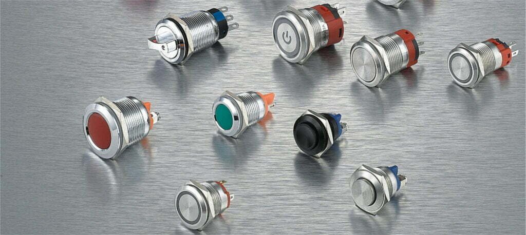
SPST push button switch structure The single-pole single-throw (SPST) push button switch is a simple switching mechanism whose structural design enables it to control the on and off of a circuit. The SPST button switch mainly consists of the following parts: Button (Actuator): This is the part that users directly contact and operate. When the button is […]
Limit switch definition A limit switch is a device that automatically controls a circuit switch when mechanical movement reaches a preset position. It is mainly used to control the extreme position of mechanical movement and detect the existence and position of objects through contact or non-contact methods. When a controlled object such as a robotic arm, conveyor […]
We use cookies to enhance your browsing experience, serve personalised ads or content, and analyse our traffic. By clicking "Accept All", you consent to our use of cookies.